3 rear panel, Warning - risk of electric shock – INFICON SQC-310 Thin Film Deposition Controller User Manual
Page 15
1 - 3
IP
N 07
4-
55
0-
P1
B
SQC-310 Operating Manual
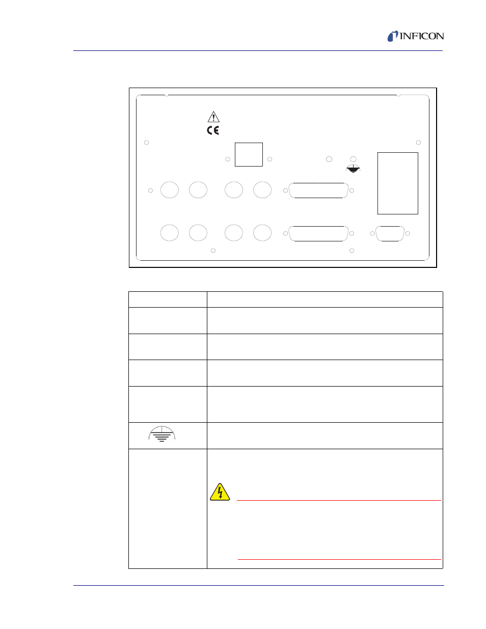
1.3 Rear Panel
Figure 1-3 Rear Panel
Table 1-2 Rear Panel Connections
Sensor 1 & 2
Connects to the oscillator. See
.
Output 1 & 2
Connects the SQC-310 output to your evaporation supply control
input (see next section).
I/O (1-8)
Connects 8 relays and 8 digital inputs to external equipment for
process control. See
RS-232
USB or Ethernet
Connects to a computer for programming and data acquisition.
RS-232 and USB are standard. Ethernet option replaces USB.
Sensor 3 & 4,
Output 3 & 4,
I/O 9-16
Increases the number of input, output, and digital I/O connections
when the optional expansion card is installed.
Measurement ground terminal useful for common system and
cable grounding.
Power Input and
Fuse
Connects to mains power. The SQC-310 automatically detects
main voltages of 100-120 and 200-240 V (ac), 50/60 Hz
WARNING - Risk Of Electric Shock
For continued protection, replace fuses
with the proper type and rating. Use
power cords only of the specified type
and rating, attached to a properly
grounded receptacle.
100-120/200-240 V~
50/60 Hz
25 VA
Sensor 1
Sensor 2
Output 1
Output 2
I/O 1-8
RS-232
Sensor 3
Sensor 4
Output 3
Output 4
I/O 9-16
Fuse T.5A 250V
SQC-310 Deposition Controller
Serial No.
USB/Ethernet