Chatsworth Products Remote Infrastructure Management (RIM-1000) User Manual
Page 38
Remote Infrastructure Management System - Version 1.0 / July 2014
38
www.chatsworth.com
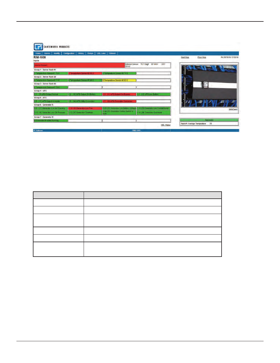
Once it’s configured, the RIM-1000 home page may look similar to this:
Figure 3.1 Configured RIM-1000 Home Page
As you can see in our example, each input has a box with its number, name, and status. The box is shaded to signal the inputs status.
Color codes are as follows.
Table 3.1 Color Definitions
Note the XML Status link in the middle right side of the page. This link allows a user to download data collected by the RIM-1000 as an
XML file and then import it into a spreadsheet for viewing, logging, and analyzing. If you’d like to save this file from the web interface,
right click on the link and select “Save Target As”. If you left click on the link, you will just be able to view the information.
Color
Description
Green
Input is normal - not in an alarm state
Yellow
Analog Inputs only - input is in a high alarm 1 or low alarm 1 state
Red
Analog input is in a high alarm 2 or low alarm 2 state. Digital input is in an alarm
state
Blue
Alarm/Input disabled by a schedule.
White (no shading)
Input is not configured-spare point for future use.
Magenta, Green, or Gold
Digital Status point is on. This color is configurable
under the System Configuration Menu.