Chatsworth Products Remote Infrastructure Management (RIM-1000) User Manual
Page 22
Remote Infrastructure Management System - Version 1.0 / July 2014
22
www.chatsworth.com
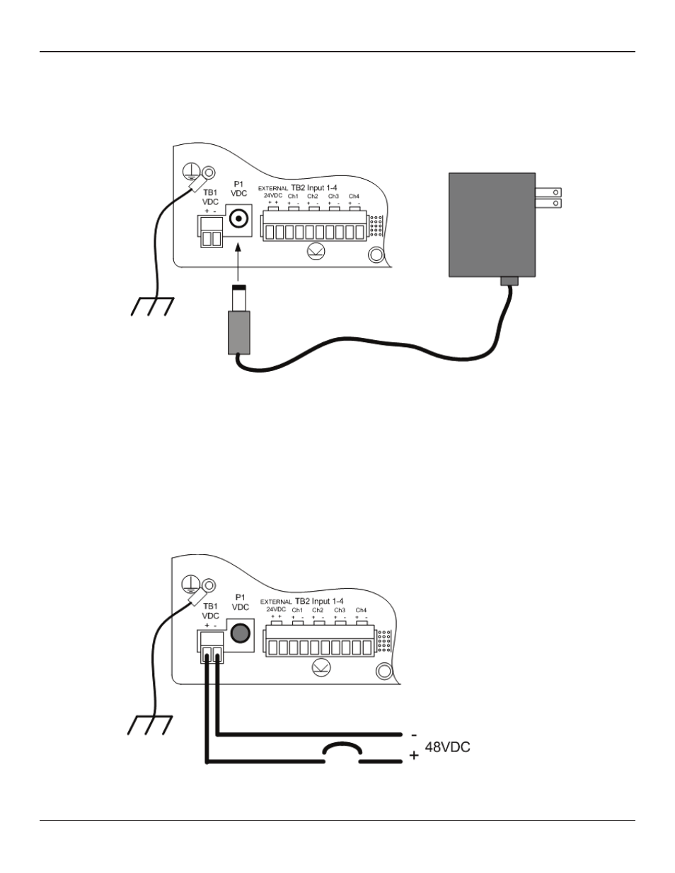
If you are installing a 24VDC model RIM-1000, plug the wall adapter into P1 and a UPS outlet as shown below. The wall adapter has a 5’
(1.524 m) power cord. CPI recommends powering the RIM-1000 from a UPS supply to allow the RIM-1000 to send alarm notification
during a power outage.
Figure 2.1 24VDC Power Supply Connection
If you are installing a 48VDC RIM-1000, the RIM-1000 must be connected to either:
a) An external 48VDC supply that can be unplugged or switched off.
b) The 48VDC supply bus via a switch or a circuit breaker. The switch or circuit breaker must be suitable located
and easily reached. It must be clearly marked as the disconnecting device for the RIM-1000.
For a 48VDC model RIM-1000, connect a 48VDC supply through a circuit breaker to TB1 as shown below. In telecommunications applica-
tions, the 48VDC supply is typically connected to the 48VDC battery system through a DC distribution panel.
Figure 2.2 48VDC Power Supply Connection