Chatsworth Products Remote Infrastructure Management (RIM-1000) User Manual
Page 112
Remote Infrastructure Management System - Version 1.0 / July 2014
112
www.chatsworth.com
When mapped, inputs appear on the map as follows:
Figure 3.56 RIM-1000 Map Key
Map Analog and Digital Input Points and Relays
1. From the RIM-1000 home page, go to Configuration>Inputs and Relays. All of your previously configured RIM-1000 inputs and
relays will display.
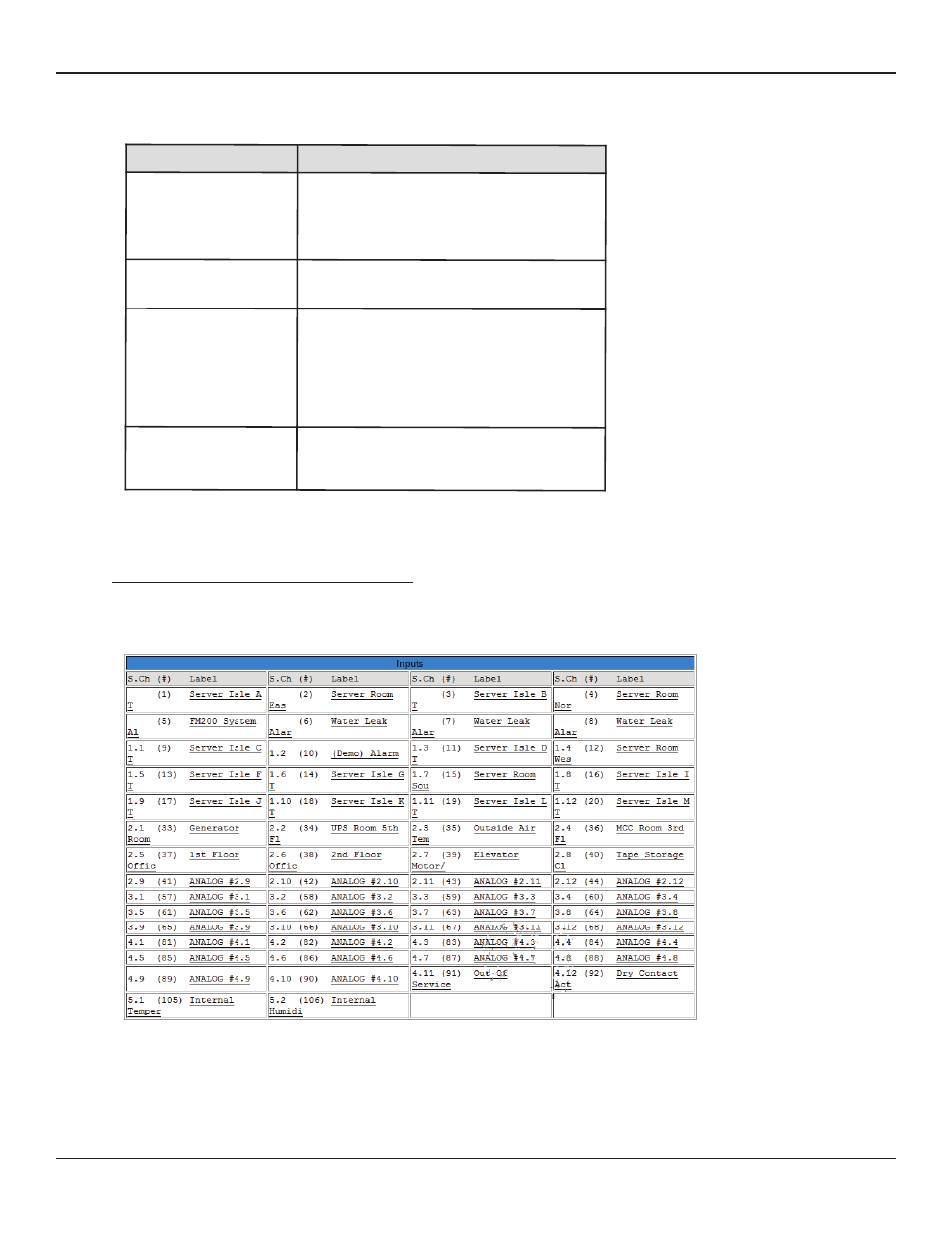
Figure 3.57 RIM-1000 Input/Output Configuration Menu
2. Click the link to take you to the Configuration screen for the input or relay you’d like to map.
Input
Map Display
Analog
Value on a colored background
Green - OK
Yellow - Stage 1 alarm
Red - Stage 2 alarm
Digital
Colored square
Red or green, represents the on/off value
Modbus/SNMP slave
Colored circle
Green - OK
Yellow - High 1 / Low 1 analog alarm
Red- Stage 2 analog alarm or digital alarm
change of state
Orange - Loss of communications
RIM-1000 Home Link
Colored circle with F in the center
Green - OK
Red - A point on the system is in alarm