Fault recovery procedure, Fault recovery procedure -5, Declare the ring to be in a “failed” state – Allied Telesis RAPIER I User Manual
Page 203
Ethernet Protection Switching Ring (EPSR)
5
Fault Recovery Procedure
When the master node detects an outage somewhere in the ring, using either of
the detection methods previously described, it will:
■
declare the ring to be in a “failed” state
■
unblock its secondary port to enable the data VLAN traffic to pass between
its primary and secondary ports.
■
flush its own forwarding database (FDB) for (only) the two ring ports
■
send an EPSR “Ring-Down-Flush-FDB” control message to all the transit
nodes, via both its primary and secondary ports
The transit nodes respond to the “Ring-Down-Flush-FDB” message by flushing
their forward databases for each of their ring ports. As the data starts to flow in
in the ring’s new configuration, each of the nodes (master and transit) re-learn
their layer 2 addresses. During this period, the master node continues to send
health check messages over the control VLAN. This situation continues until
the faulty link or node is repaired.
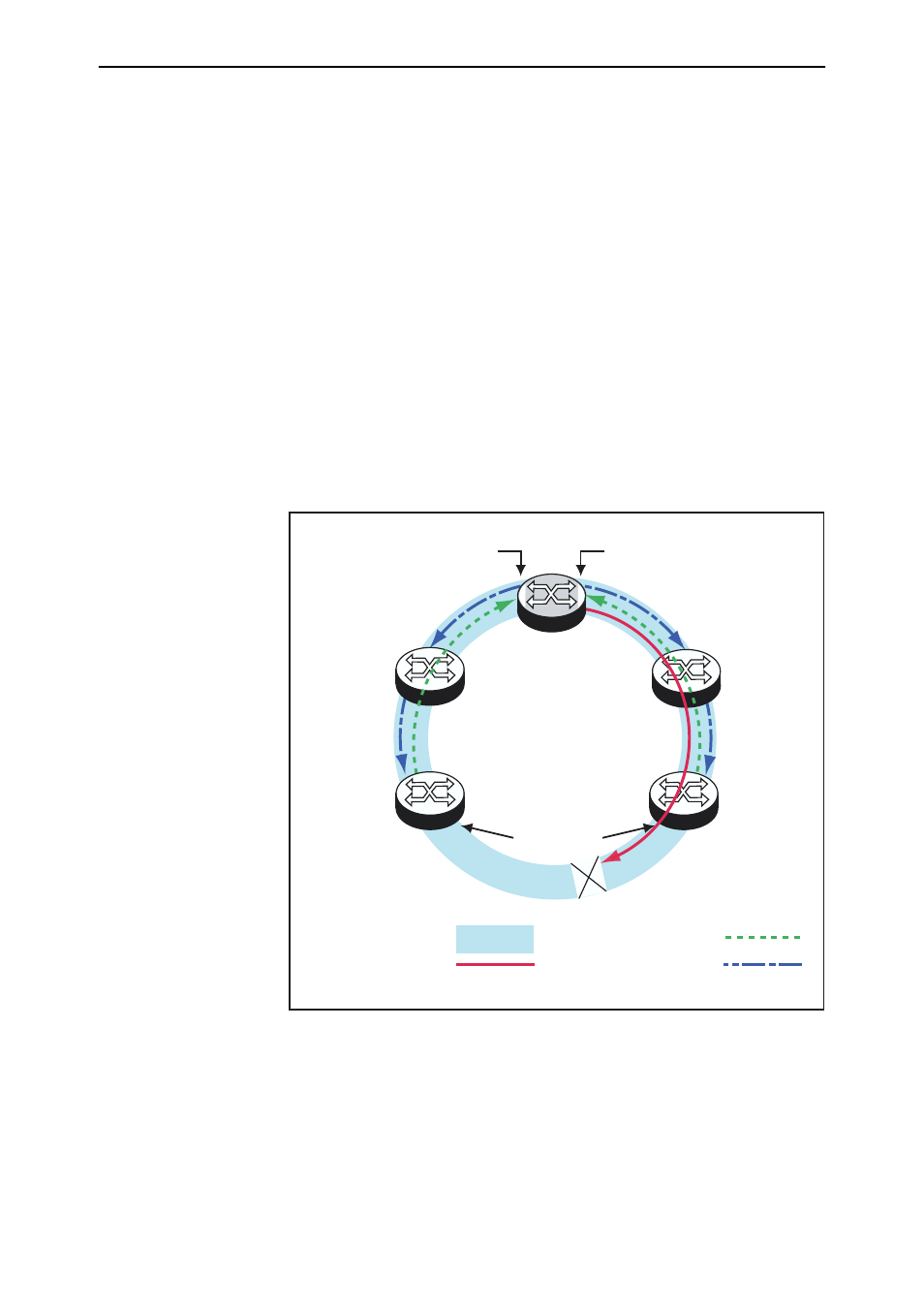
Figure 1-2
shows the flow of control frames
under fault conditions.
Figure 1-2: EPSR Fault Detection Messages
For a multi domain ring, this process will occur separately for each domain
within the ring.
Master
Node
Transit
Node
1
Transit
Node
4
Transit
Node
2
Master Node Hello Message
Control VLAN
Ring-Down-Flush-FDB Message
Transit
Node
3
EPSR 2.eps
Control Vlan “forwarding”
Data VLANs “forwarding”
Control VLAN “forwarding”
Data VLANs
“move from blocking to forwarding”
Data Ports move from
fowarding to blocking
Transit Node Links Down Message
P
S
(1)
(2)
(3)