X1 - m12, 8-pole circular connector, . x1.-.m12,.8-pole.circular.connector – Burkert Type 8793 User Manual
Page 213
213
DeviceNet
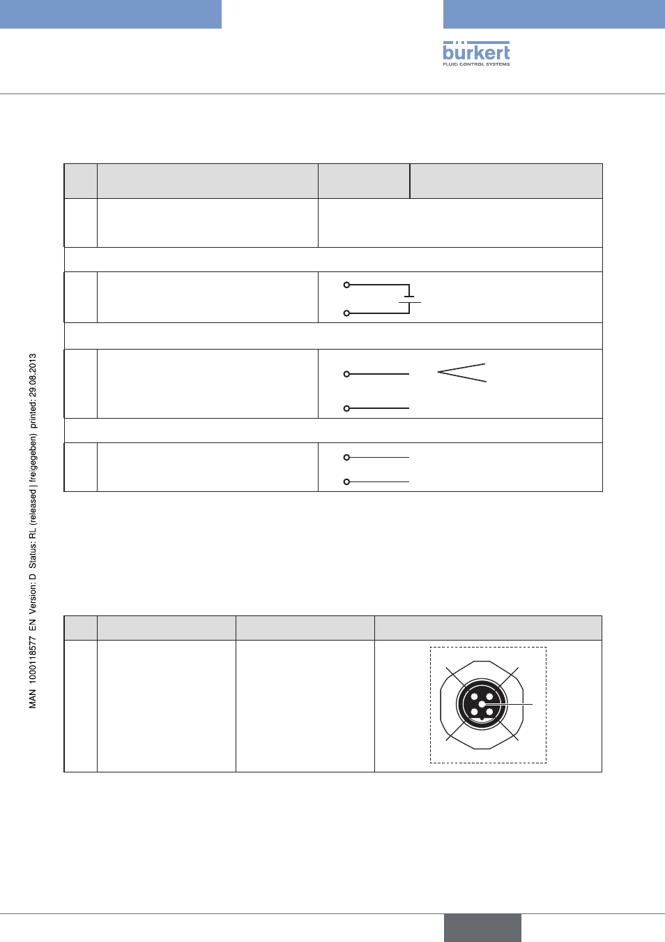
32.3. X1 - M12, 8-pole circular connector
Pin
Configuration
On.the.device.
side
External.circuit./.Signal.level
1
not used
2
not used
Operating.voltage
3
GND
3
24 V DC ± 10%
max. residual ripple 10%
4
+24 V
4
Input.signals.of.the.control.centre.(e.g..PLC)
5
Binary input +
5
+
0 – 5 V (log. 0)
10 – 30 V (log. 1)
6
Binary input –
6
GND (identical with Pin 3)
Output.signals.to.the.control.centre.(e.g..PLC).-.(only.used.for.binary.output.option)
7
Binary output 1 (referring to Pin 3)
7
0 – 24 V
8
Binary output 2 (referring to Pin 3)
8
0 – 24 V
Table 112:
Pin assignment; X1 - M12, 8-pole circular connector DeviceNet
32.4. X3 - M12, 5-pole circular connector - bus
connection
Pin
Signal
Colour
Configuration
1
Shielding
not used
2
3
4
1
5
2
V +
not used
3
V –
not used
4
CAN H
white
5
CAN L
blue
Table 113:
Pin assignment; X3 - M12, 5-pole circular connector - bus connection; DeviceNet
english
Type 8792, 8793