Board level cameras: pulse-width modulation, Table 31: pwm configura, Tion registers – ALLIED Vision Technologies Guppy F-503 User Manual
Page 90
Camera interfaces
GUPPY Technical Manual V7.1.0
90
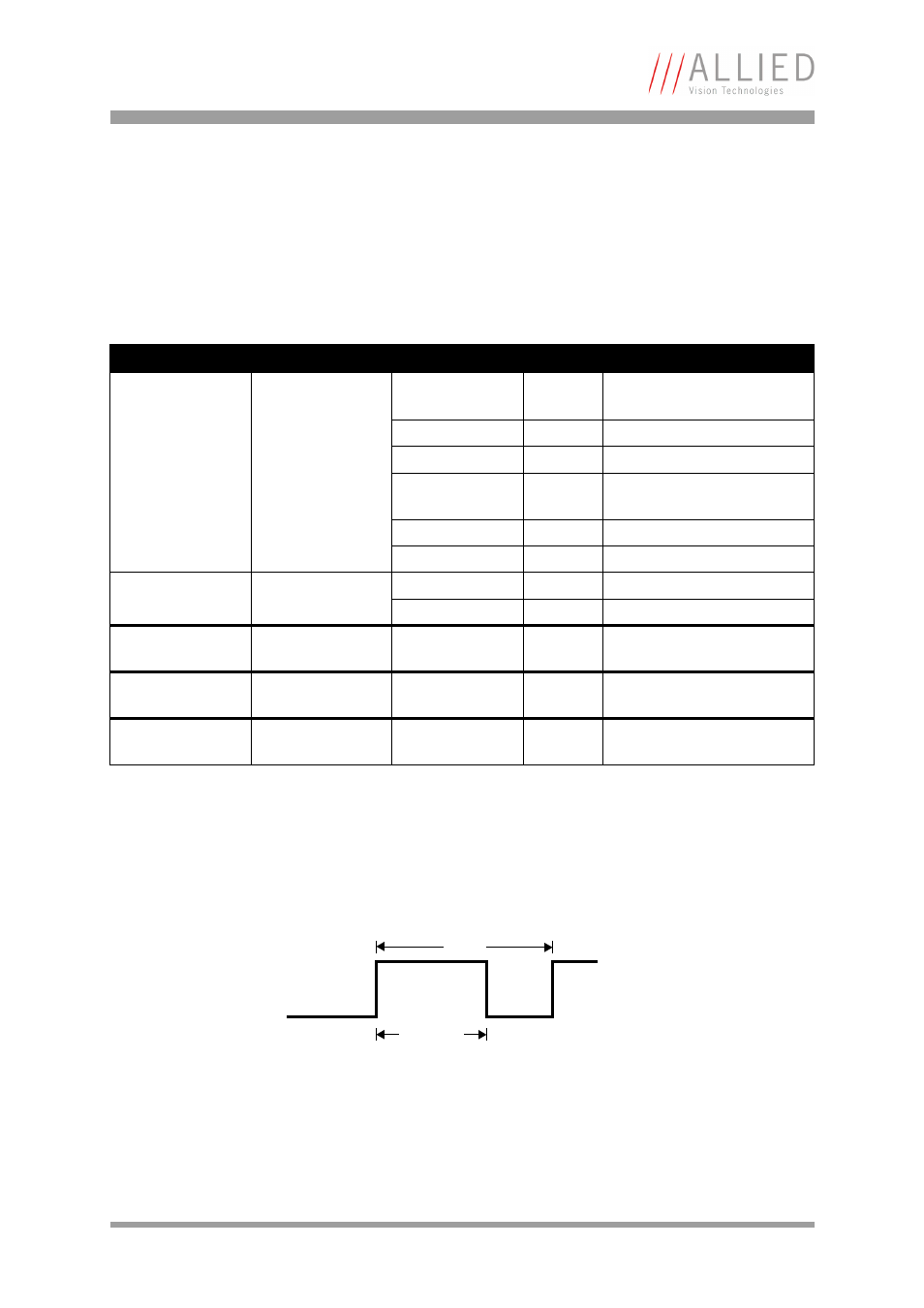
Board level cameras: pulse-width modulation
The 4 inputs and 4 outputs are independent. Each output has pulse-width
modulation (PWM) capabilities, which can be used (with additional external
electronics) for motorized speed control or autofocus control.
Period (in µs) and pulse width (in µs) are adjustable via the following regis-
ters (see also examples in Chapter
To enable the PWM feature select output mode 0x09. Control the signal state
via the PulseWidth and Period fields (all times in microseconds (µs)).
Register
Name
Field
Bit
Description
0xF1000800
IO_OUTP_PWM1
Presence_Inq
[0]
Indicates presence of this
feature (read only)
---
[1]
Reserved
---
[2..3]
Reserved
MinPeriod
[4..19]
Minimum PWM period in µs
(read only)
---
[20..27]
Reserved
---
[28..31]
Reserved
0xF1000804
PulseWidth
[0..15]
PWM pulse width in µs
Period
[16..31]
PWM period in µs
0xF1000808
IO_OUTP_PWM2
Same as
IO_OUTP_PWM1
0xF100080C
IO_OUTP_PWM3
Same as
IO_OUTP_PWM1
0xF1000810
IO_OUTP_PWM4
Same as
IO_OUTP_PWM1
Table 31: PWM configuration registers
Figure 40: PulseWidth and Period definition
PulseWidth
Period