Ooisensors flash delay, Setting the integration time – Ocean Optics OOISensors User Manual
Page 110
6: Hardware Data Sheets and Instructions
• The switch is turned to pulsed mode
• There is a jumper over the pins in JP1 of the R-LS-450
• There is a jumper over the CS pins in JP2 of the R-LS-450
• There is a jumper over the over the Remote pins in JP3 of the R-LS-450
• There is a jumper over pins labeled /16, /14, /12, or /10 in JP3 of the S2000, depending on the pulse
rate you need. The pulses per second are also dependent upon the frequency of your A/D converter.
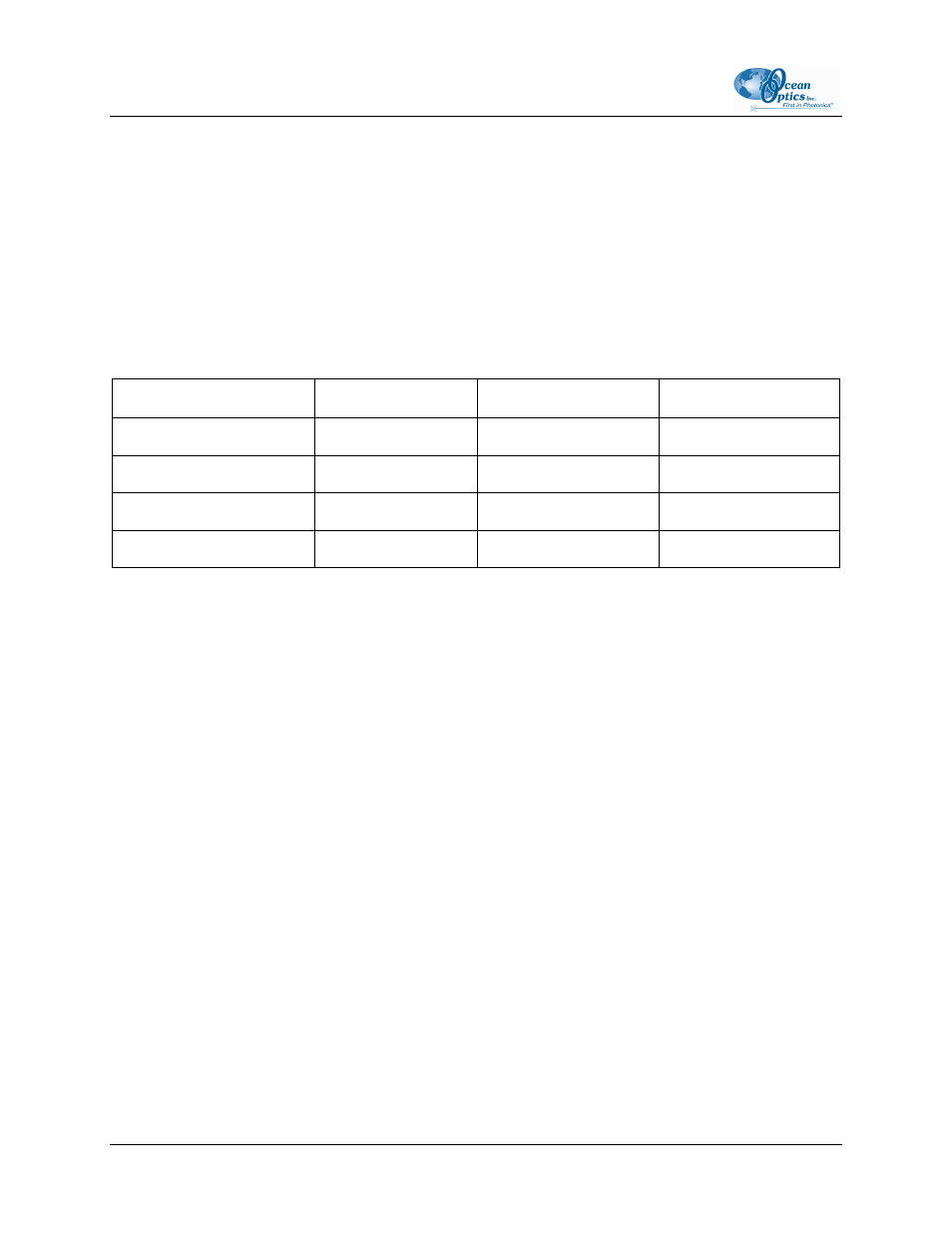
See the table below for configuration choices:
Pulse Mode Configuration Options for A/D Converters
Pins on the S2000’s JP3
DAQ700
SAD500
ADC1000
/16 1.5
7.6
15.2
/14 6.1
30.4
60.8
/12 24.0
122.0
244.0
/10 98.0
488.0
976.0
OOISensors Flash Delay
You can control the pulses per second of the R-LS-450 through the Flash Delay function in the
OOISensors Software if the following conditions are met:
• You are using an ADC1000 A/D converter
• The switch is turned to pulsed mode
• There is a jumper over the pins in JP1 on the R-LS-450 board
• There is a jumper over the pins labeled CS in JP2 on the R-LS-450 board
• There is a jumper over the pins labeled Remote in JP3 on the R-LS-450 board
• There is a jumper over the pins labeled 2 in JP3 on the S2000 board
Setting the Integration Time
When using any of the pulsed modes for the R-LS-450, you need to ensure that a constant number of
flashes occurs for every integration cycle. This achieves a continuous and stable signal. Set the
appropriate integration time in the OOISensors Software.
To achieve a constant number of flashes per integration cycle, the integration time must be a multiple of
those shown in the table below, according to the A/D converter being used:
100
FOXY-AL300-000-02-0207