Rainbow Electronics ATmega64M1 User Manual
Page 55
55
8209A–AVR–08/09
ATmega16M1/32M1/64M1
Notes:
1. When the BOOTRST Fuse is programmed, the device will jump to the Boot Loader address at
“Boot Loader Support – Read-While-Write Self-Programming” on page 272
2. When the IVSEL bit in MCUCR is set, Interrupt Vectors will be moved to the start of the Boot
Flash Section. The address of each Interrupt Vector will then be the address in this table
added to the start address of the Boot Flash Section.
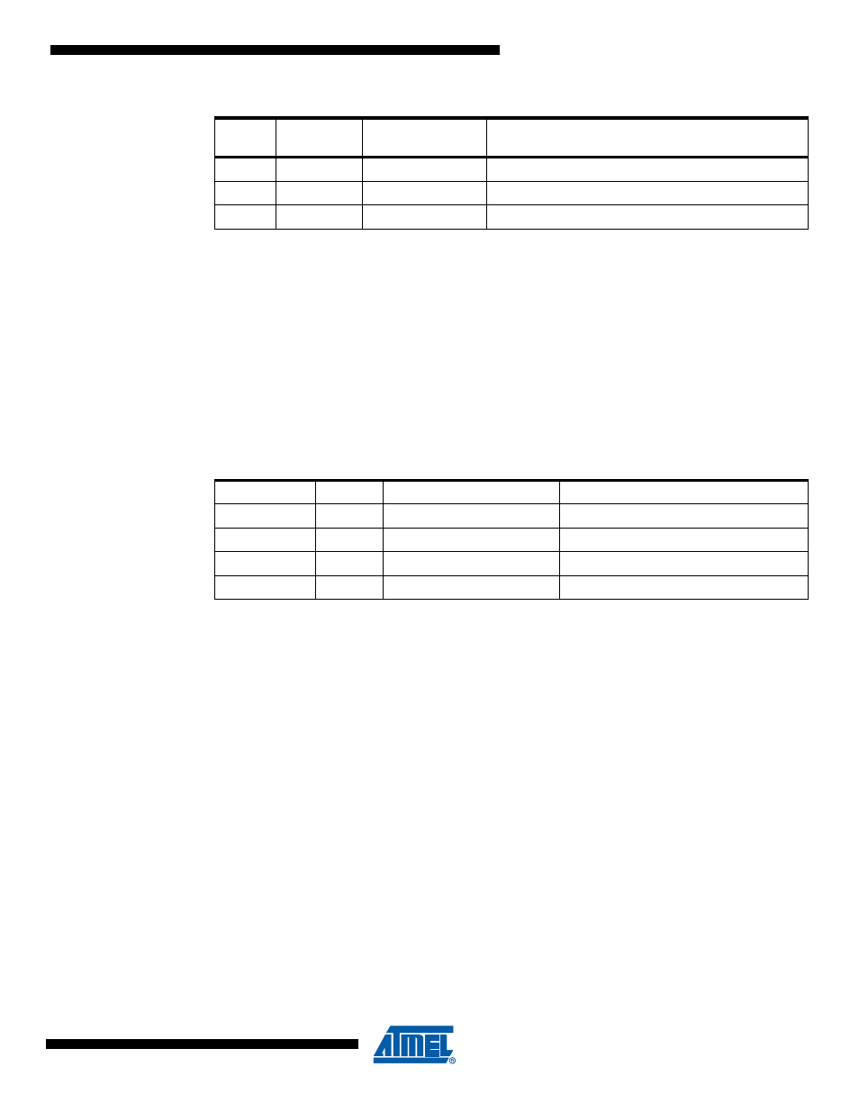
shows reset and Interrupt Vectors placement for the various combinations of
BOOTRST and IVSEL settings. If the program never enables an interrupt source, the Interrupt
Vectors are not used, and regular program code can be placed at these locations. This is also
the case if the Reset Vector is in the Application section while the Interrupt Vectors are in the
Boot section or vice versa.
Note:
1. The Boot Reset Address is shown in
. For the BOOTRST Fuse “1”
means unprogrammed while “0” means programmed.
The most typical and general program setup for the Reset and Interrupt Vector Addresses in
ATmega16M1/32M1/64M1 is:
Address
Labels Code
Comments
0x000
jmp
RESET
; Reset Handler
0x002
jmp
ANA_COMP_0
; Analog Comparator 0 Handler
0x004
jmp
ANA_COMP_1
; Analog Comparator 1 Handler
0x006
jmp
ANA_COMP_2
; Analog Comparator 2 Handler
0x008
jmp
ANA_COMP_3
; Analog Comparator 3 Handler
0x00A
jmp
PSC_FAULT
; PSC Fault Handler
0x00C
jmp
PSC_EC
; PSC End of Cycle Handler
0x00E
jmp
EXT_INT0
; IRQ0 Handler
0x010
jmp
EXT_INT1
; IRQ1 Handler
0x012
jmp
EXT_INT2
; IRQ2 Handler
0x014
jmp
EXT_INT3
; IRQ3 Handler
0x016
jmp
TIM1_CAPT
; Timer1 Capture Handler
0x018
jmp
TIM1_COMPA
; Timer1 Compare A Handler
0x01A
jmp
TIM1_COMPB
; Timer1 Compare B Handler
29
0x0038
WDT
Watchdog Time-Out Interrupt
30
0x003A
EE READY
EEPROM Ready
31
0x003C
SPM READY
Store Program Memory Ready
Table 12-2.
Reset and Interrupt Vectors Placement in ATmega16M1/32M1/64M1
BOOTRST
IVSEL
Reset Address
Interrupt Vectors Start Address
1
0
0x000
0x001
1
1
0x000
Boot Reset Address + 0x002
0
0
Boot Reset Address
0x001
0
1
Boot Reset Address
Boot Reset Address + 0x002
Table 12-1.
Reset and Interrupt Vectors
Vector
No.
Program
Address
Source
Interrupt Definition