2 external reset, 3 brown-out detection – Rainbow Electronics ATmega64M1 User Manual
Page 45
45
8209A–AVR–08/09
ATmega16M1/32M1/64M1
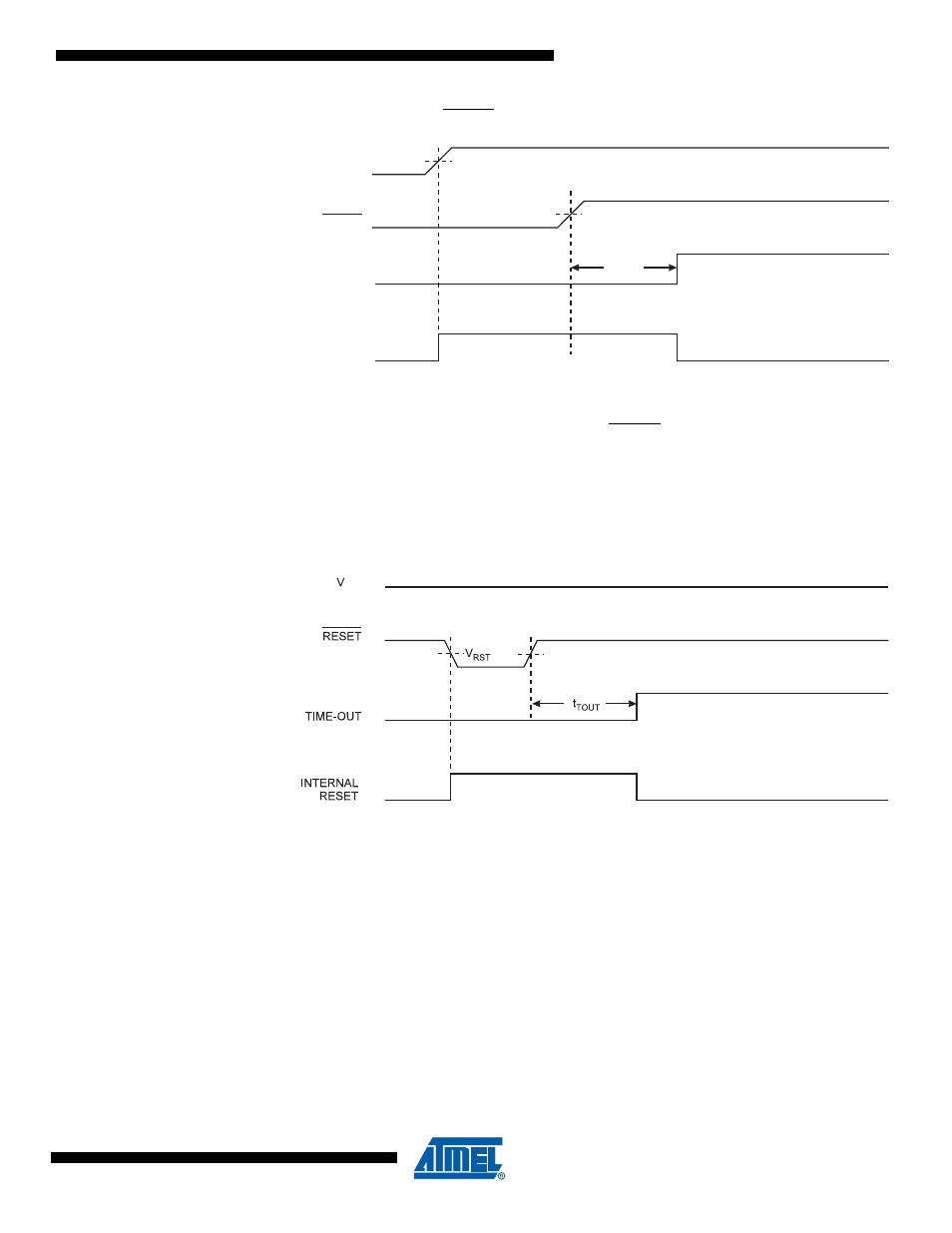
Figure 11-3. MCU Start-up, RESET Extended Externally
11.2.2
External Reset
An External Reset is generated by a low level on the RESET pin. Reset pulses longer than the
minimum pulse width (see
“System and Reset Characteristics” on page 313
) will generate a
reset, even if the clock is not running. Shorter pulses are not guaranteed to generate a reset.
When the applied signal reaches the Reset Threshold Voltage – V
RST
– on its positive edge, the
delay counter starts the MCU after the Time-out period – t
TOUT
–
has expired.
Figure 11-4. External Reset During Operation
11.2.3
Brown-out Detection
ATmega16M1/32M1/64M1 has an On-chip Brown-out Detection (BOD) circuit for monitoring the
V
CC
level during operation by comparing it to a fixed trigger level. The trigger level for the BOD
can be selected by the BODLEVEL Fuses. The trigger level has a hysteresis to ensure spike
free Brown-out Detection. The hysteresis on the detection level should be interpreted as V
BOT+
=
V
BOT
+ V
HYST
/2 and V
BOT-
= V
BOT
- V
HYST
/2.
When the BOD is enabled, and V
CC
decreases to a value below the trigger level (V
BOT-
in
), the Brown-out Reset is immediately activated. When V
CC
increases above the trigger
level (V
BOT+
in
), the delay counter starts the MCU after the Time-out period t
TOUT
has
expired.
The BOD circuit will only detect a drop in V
CC
if the voltage stays below the trigger level for lon-
ger than t
BOD
given in
“System and Reset Characteristics” on page 313
.
RESET
TIME-OUT
INTERNAL
RESET
t
TOUT
V
POT
V
RST
V
CC
CC