4 register description, 1 gtccr – general timer/counter control register – Rainbow Electronics ATmega64M1 User Manual
Page 133
133
8209A–AVR–08/09
ATmega16M1/32M1/64M1
17.4
Register Description
17.4.1
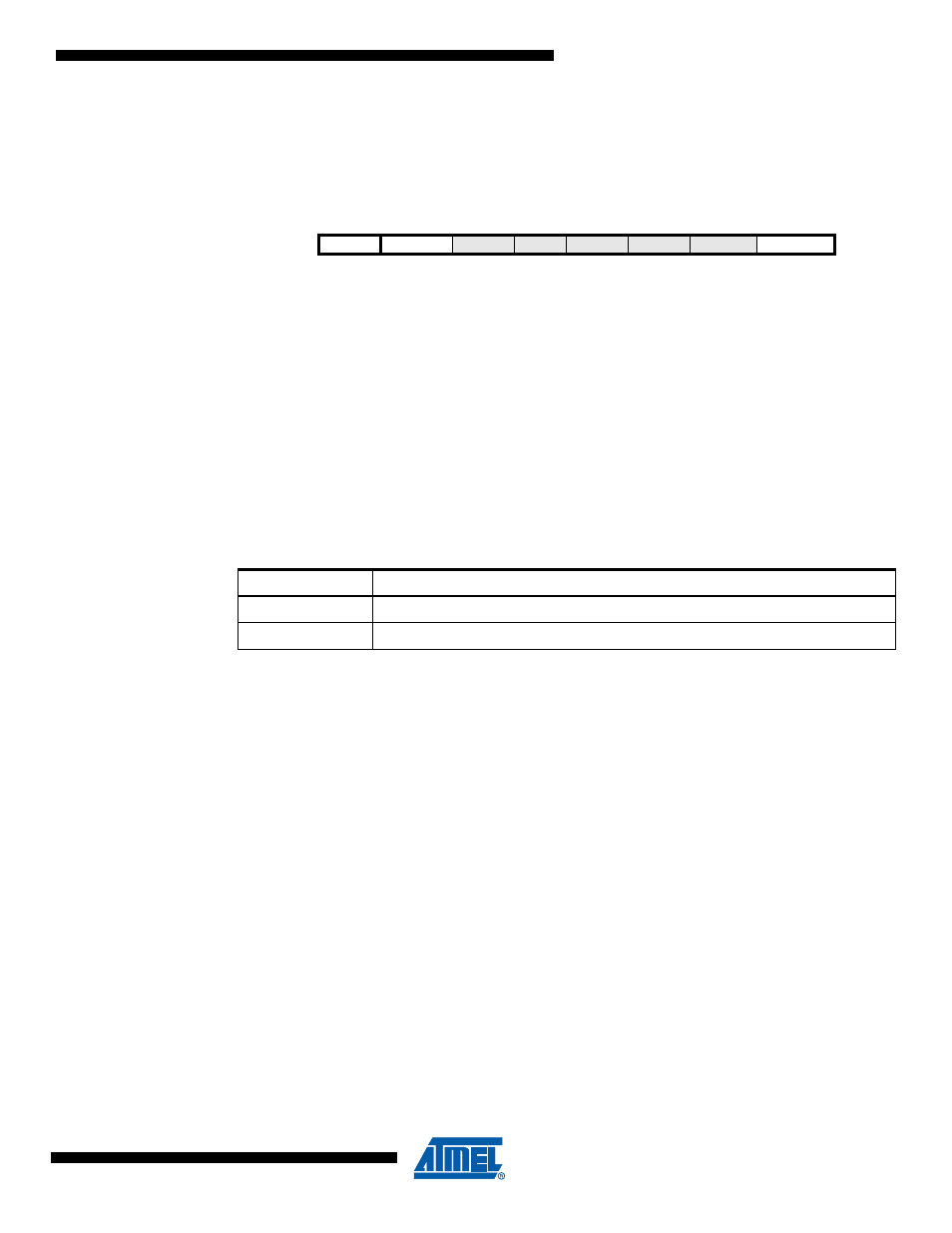
GTCCR – General Timer/Counter Control Register
• Bit 7 – TSM: Timer/Counter Synchronization Mode
Writing the TSM bit to one activates the Timer/Counter Synchronization mode. In this mode, the
value that is written to the PSRSYNC bit is kept, hence keeping the corresponding prescaler
reset signals asserted. This ensures that the corresponding Timer/Counters are halted and can
be configured to the same value without the risk of one of them advancing during configuration.
When the TSM bit is written to zero, the PSRSYNC bit is cleared by hardware, and the
Timer/Counters start counting simultaneously.
• Bit6 – ICPSEL1:
Timer 1 Input Capture selection
Timer 1 capture function has two possible inputs ICP1A (PD4) and ICP1B (PC3). The selection
is made thanks to ICPSEL1 bit as described in
• Bit 0 – PSRSYNC: Prescaler Reset
When this bit is one, Timer/Counter1 and Timer/Counter0 prescaler will be Reset. This bit is nor-
mally cleared immediately by hardware, except if the TSM bit is set. Note that Timer/Counter1
and Timer/Counter0 share the same prescaler and a reset of this prescaler will affect both
timers.
Bit
7
6
5
4
3
2
1
0
TSM
ICPSEL1
–
–
–
–
–
PSRSYNC
GTCCR
Read/Write
R/W
R/W
R
R
R
R
R
R/W
Initial Value
0
0
0
0
0
0
0
0
Table 17-1.
ICPSEL1
ICPSEL1
Description
0
Select ICP1A as trigger for timer 1 input capture
1
Select ICP1B as trigger for timer 1 input capture