5 lin / uart description, 1 reset, 2 clock – Rainbow Electronics ATmega64M1 User Manual
Page 208: 3 lin protocol selection, 4 configuration
208
8209A–AVR–08/09
ATmega16M1/32M1/64M1
21.5
LIN / UART Description
21.5.1
Reset
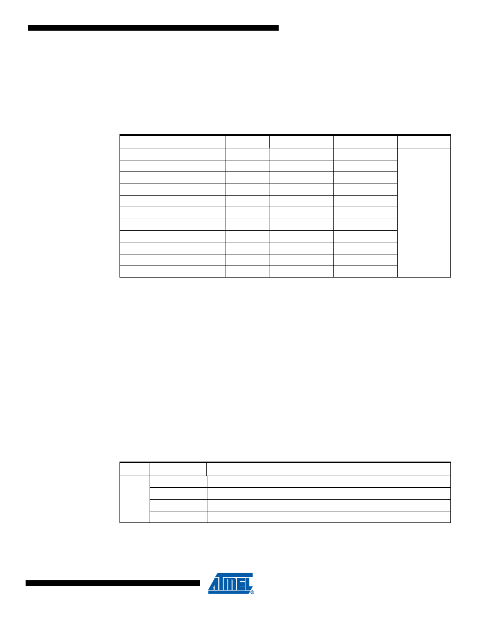
The AVR core reset logic signal also resets the LIN/UART controller. Another form of reset
exists, a software reset controlled by LSWRES bit in LINCR register. This self-reset bit performs
a partial reset as shown in
.
21.5.2
Clock
The I/O clock signal (clk
i/o
) also clocks the LIN/UART controller. It is its unique clock.
21.5.3
LIN Protocol Selection
LIN13 bit in LINCR register is used to select the LIN protocol:
• LIN13 = 0 (default): LIN 2.1 protocol,
• LIN13 = 1: LIN 1.3 protocol.
The controller checks the LIN13 bit in computing the checksum (enhanced checksum in LIN2.1 /
classic checksum in LIN 1.3). See
“Rx & TX Response Functions” on page 206
.
This bit is irrelevant for UART commands.
21.5.4
Configuration
Depending on the mode (LIN or UART), LCONF[1..0] bits of the LINCR register set the controller
in the following configuration (
):
Table 21-2.
Reset of LIN/UART Registers
Register
Name
Reset Value
LSWRES Value
Comment
LIN Control Reg.
LINCR
0000 0000
b
0000 0000
b
x=unknown
u=unchanged
LIN Status & Interrupt Reg.
LINSIR
0000 0000
b
0000 0000
b
LIN Enable Interrupt Reg.
LINENIR
0000 0000
b
xxxx 0000
b
LIN Error Reg.
LINERR
0000 0000
b
0000 0000
b
LIN Bit Timing Reg.
LINBTR
0010 0000
b
0010 0000
b
LIN Baud Rate Reg. Low
LINBRRL
0000 0000
b
uuuu uuuu
b
LIN Baud Rate Reg. High
LINBRRH
0000 0000
b
xxxx uuuu
b
LIN Data Length Reg.
LINDLR
0000 0000
b
0000 0000
b
LIN Identifier Reg.
LINIDR
1000 0000
b
1000 0000
b
LIN Data Buffer Selection
LINSEL
0000 0000
b
xxxx 0000
b
LIN Data
LINDAT
0000 0000
b
0000 0000
b
Table 21-3.
Configuration Table versus Mode
Mode
LCONF[1..0]
Configuration
LIN
00
b
LIN standard configuration (default)
01
b
No CRC field detection or transmission
10
b
Frame_Time_Out disable
11
b
Listening mode