Rainbow Electronics ATmega64M1 User Manual
Page 268
268
8209A–AVR–08/09
ATmega16M1/32M1/64M1
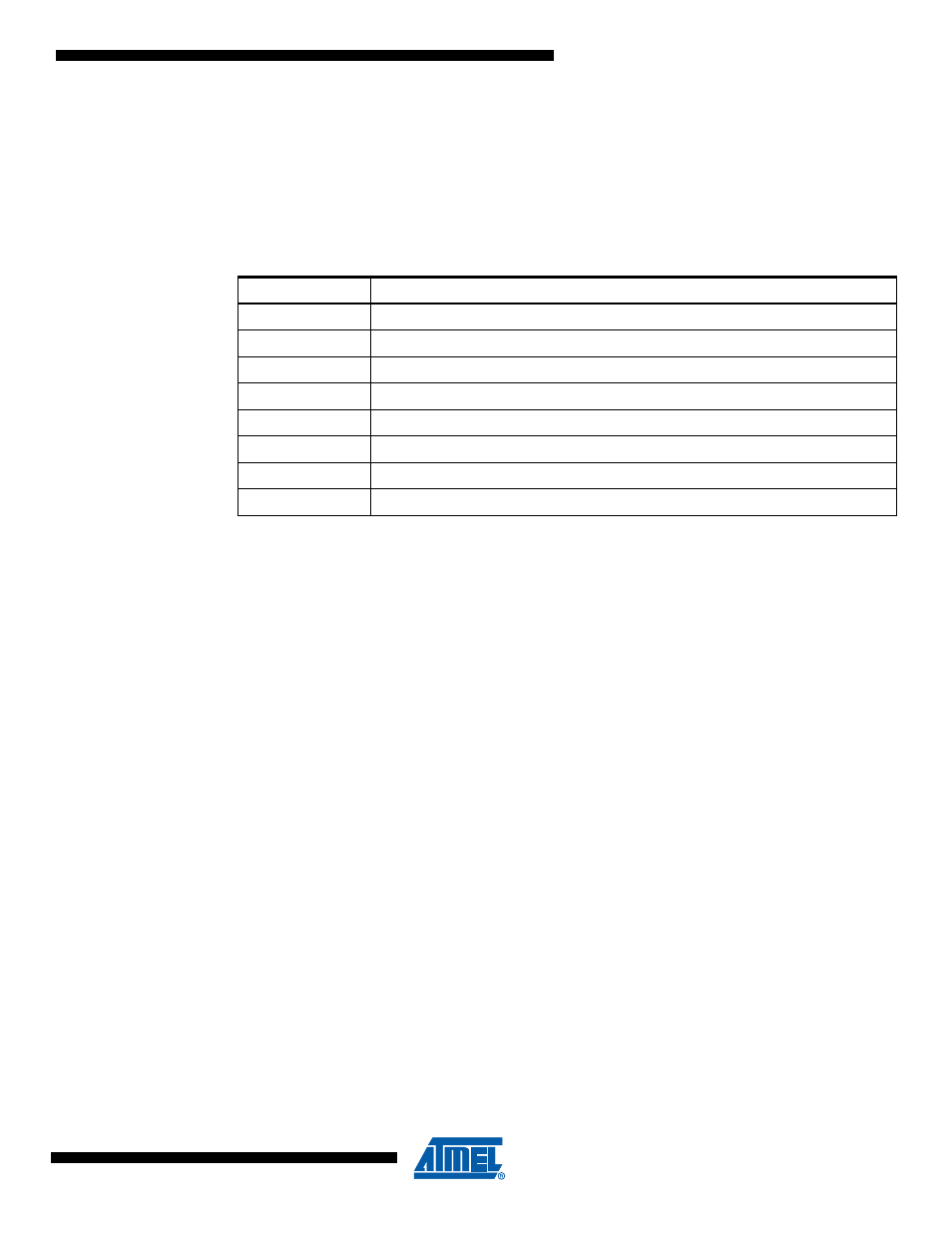
• Bit 6:4 – DATS[2:0]: DAC Trigger Selection bits
These bits are only necessary in case the DAC works in auto trigger mode. It means if DAATE
bit is set.
In accordance with the
, these 3 bits select the interrupt event which will generate the
update of the DAC input values. The update will be generated by the rising edge of the selected
interrupt flag whether the interrupt is enabled or not.
• Bit 2 – DALA: Digital to Analog Left Adjust
Set this bit to left adjust the DAC input data.
Clear it to right adjust the DAC input data.
The DALA bit affects the configuration of the DAC data registers. Changing this bit affects the
DAC output on the next DACH writing.
• Bit 1 – DAOE: Digital to Analog Output Enable bit
Set this bit to output the conversion result on D2A,
Clear it to use the DAC internally.
• Bit 0 – DAEN: Digital to Analog Enable bit
Set this bit to enable the DAC,
Clear it to disable the DAC.
25.5.2
DACH and DACL – Digital to Analog Converter input Register
DACH and DACL registers contain the value to be converted into analog voltage.
Writing the DACL register prohibits the update of the input value until DACH has not been writ-
ten too. So the normal way to write a 10-bit value in the DAC register is firstly to write DACL the
DACH.
In order to work easily with only 8 bits, there is the possibility to left adjust the input value. Like
this it is sufficient to write DACH to update the DAC value.
Table 25-1.
DAC Auto Trigger source selection
DATS[2:0]
Description
000
Analog comparator 0
001
Analog comparator 1
010
External Interrupt Request 0
011
Timer/Counter0 Compare Match
100
Timer/Counter0 Overflow
101
Timer/Counter1 Compare Match B
110
Timer/Counter1 Overflow
111
Timer/Counter1 Capture Event