3 handling lbt[5:0, 7 data length, 1 data length in lin 2.1 – Rainbow Electronics ATmega64M1 User Manual
Page 211
211
8209A–AVR–08/09
ATmega16M1/32M1/64M1
The new LBT[5..0] value will be used up to the end of the response. Then, the LBT[5..0] will be
reset to 32 for the next header.
The LINBTR register can be used to re-calibrate the clock oscillator.
The re-synchronization is not performed if the LIN node is enabled as a master.
21.5.6.3
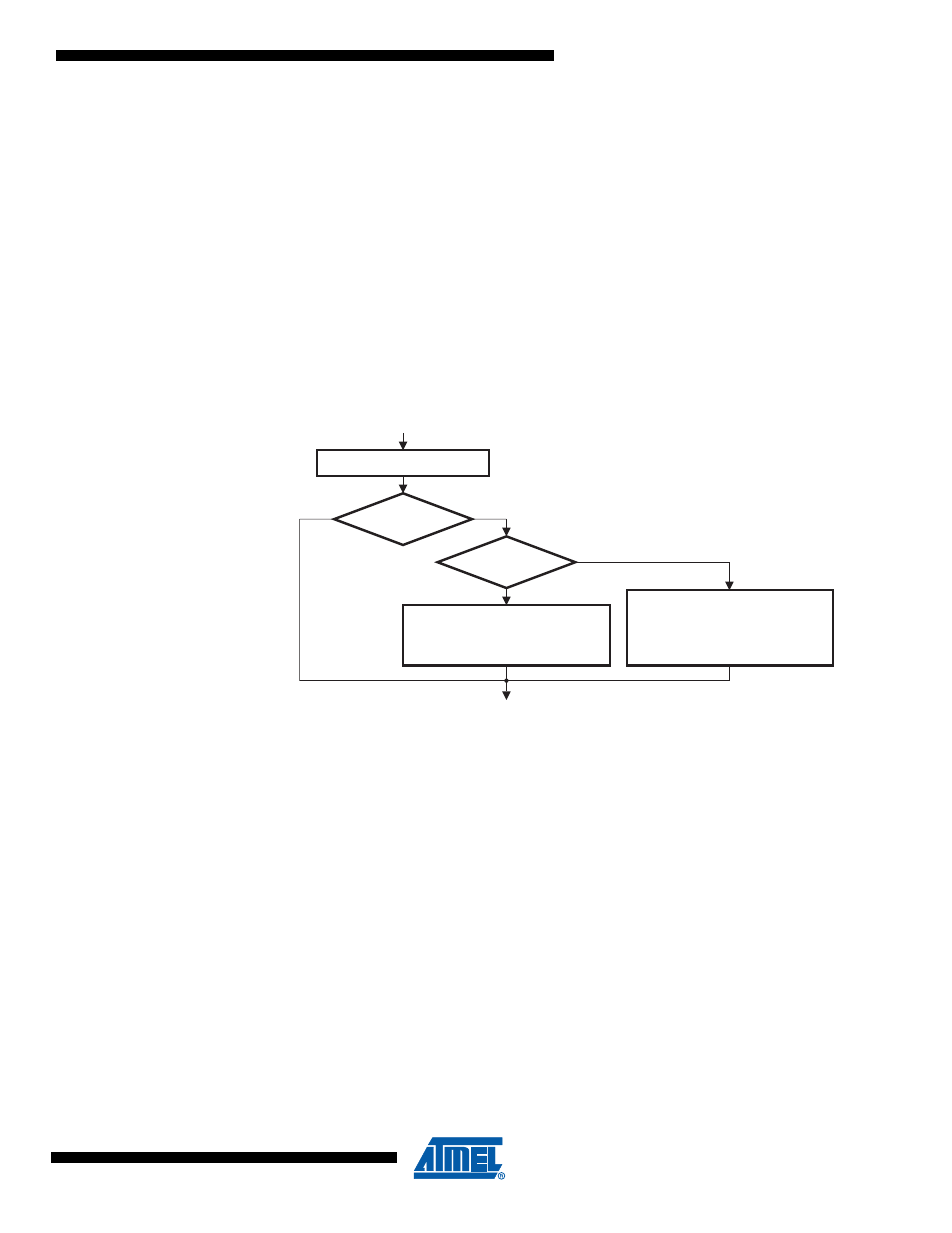
Handling LBT[5:0]
LDISR bit of LINBTR register is used to:
• To enable the setting of LBT[5:0] (to manually adjust the baud rate especially in the case of
UART mode). A minimum of 8 is required for LBT[5:0] due to the sampling operation.
• Disable the re-synchronization in LIN Slave Mode for test purposes.
Note that the LENA bit of LINCR register is important for this handling (see
).
Figure 21-8. Handling LBT[5:0]
21.5.7
Data Length
Section 21.4.6 “LIN Commands” on page 205
describes how to set or how are automatically set
the LRXDL[3..0] or LTXDL[3..0] fields of LINDLR register before receiving or transmitting a
response.
In the case of Tx Response the LRXDL[3..0] will be used by the hardware to count the number of
bytes already successfully sent.
In the case of Rx Response the LTXDL[3..0] will be used by the hardware to count the number of
bytes already successfully received.
If an error occurs, this information is useful to the programmer to recover the LIN messages.
21.5.7.1
Data Length in LIN 2.1
• If LTXDL[3..0]=0 only the CHECKSUM will be sent,
• If LRXDL[3..0]=0 the first byte received will be interpreted as the CHECKSUM,
• If LTXDL[3..0] or LRXDL[3..0] >8, values will be forced to 8 after the command setting and
before sending or receiving of the first byte.
Write in LINBTR register
LENA ?
(LINCR bit 4)
LDISR
to write
=0
=0
=1
LBT[5..0] forced to 0x20
LDISR forced to 0
Enable re-synch. in LIN mode
LBT[5..0] = LBT[5..0] to write
(LBT[5..0]
min
=8)
LDISR forced to 1
Disable re-synch. in LIN mode
=1