5 data length after error, 6 data length in uart mode, 8 xxok flags – Rainbow Electronics ATmega64M1 User Manual
Page 213
213
8209A–AVR–08/09
ATmega16M1/32M1/64M1
• The user initializes LTXDL field before setting the Tx Response command,
• After setting the Tx Response command, LRXDL is reset by hardware,
• LTXDL will remain unchanged during Tx (during busy signal),
• LRXDL will count the number of transmitted bytes (during busy signal),
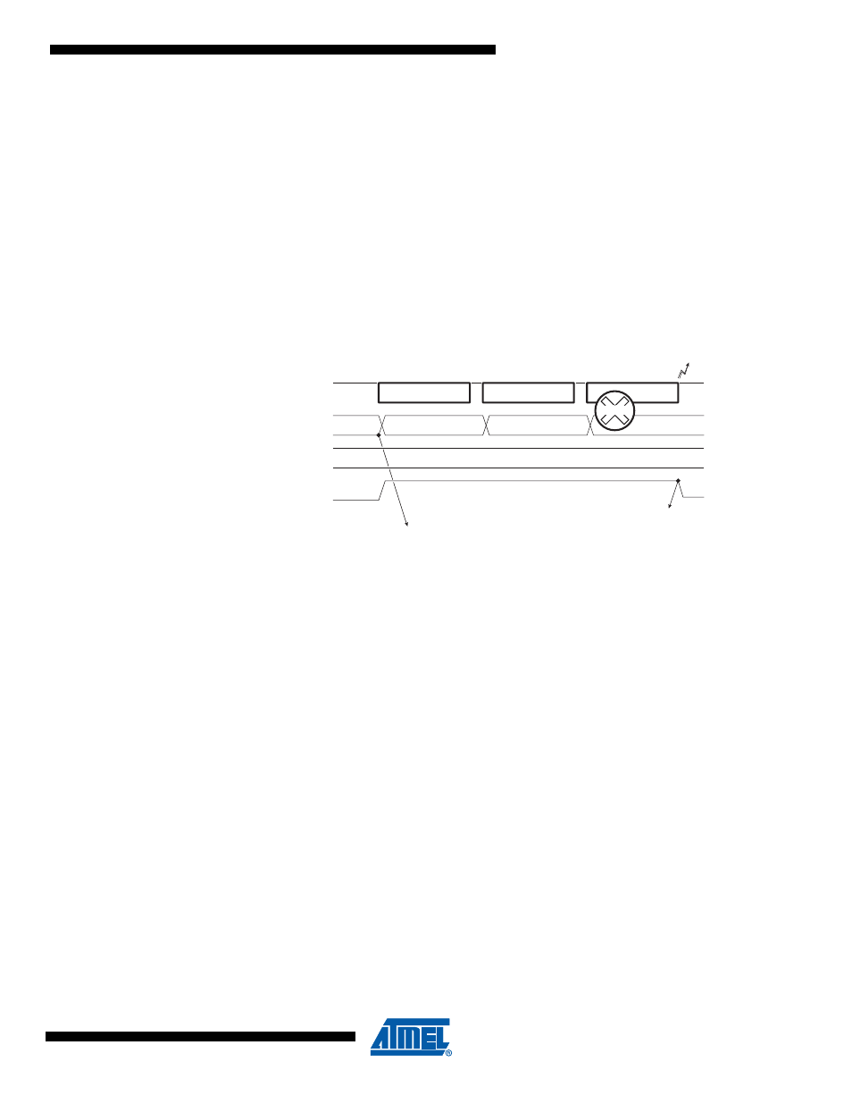
• If an error occurs, Tx stops, the corresponding error flag is set and LRXDL will give the
number of transmitted bytes without error,
• If no error occurs, LTXOK is set after the transmission of the CHECKSUM, LTXDL will be
unchanged (and LRXDL = LTXDL).
21.5.7.5
Data Length after Error
Figure 21-11. Tx Response - Error
Note:
Information on response (ex: error on byte) is only available at the end of the serialization/de-seri-
alization of the byte.
21.5.7.6
Data Length in UART Mode
• The UART mode forces LRXDL and LTXDL to 0 and disables the writing in LINDLR register,
• Note that after reset, LRXDL and LTXDL are also forced to 0.
21.5.8
xxOK Flags
There are three xxOK flags in LINSIR register:
• LIDOK: LIN IDentifier OK
It is set at the end of the header, either by the Tx Header function or by the Rx Header. In LIN
1.3, before generating LIDOK, the controller updates the LRXDL & LTXDL fields in LINDLR
register.
It is not driven in UART mode.
• LRXOK: LIN RX response complete
It is set at the end of the response by the Rx Response function in LIN mode and once a
character is received in UART mode.
• LTXOK: LIN TX response complete
It is set at the end of the response by the Tx Response function in LIN mode and once a
character has been sent in UART mode.
These flags can generate interrupts if the corresponding enable interrupt bit is set in the LINE-
NIR register (see
Section 21.5.13 “Interrupts” on page 216
).
DATA-0
DATA-1
LCMD2..0=000
b
LIN bus
LBUSY
1
st
Byte
2
nd
Byte
3
rd
Byte
LERR
1
4
0
LRXDL
2
LCMD=Tx Response
LTXDL
4
DATA-2
ERROR