5 busy signal, 1 busy signal in lin mode, Txlin rxlin – Rainbow Electronics ATmega64M1 User Manual
Page 209: Tx lin, Rx lin listen
209
8209A–AVR–08/09
ATmega16M1/32M1/64M1
The LIN configuration is independent of the programmed LIN protocol.
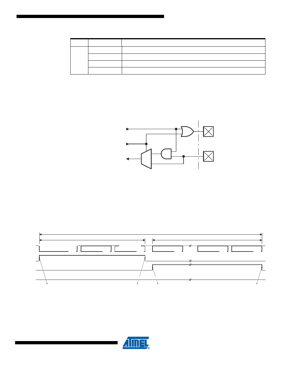
The listening mode connects the internal Tx LIN and the internal Rx LIN together. In this mode,
the TXLIN output pin is disabled and the RXLIN input pin is always enabled. The same scheme
is available in UART mode.
Figure 21-6. Listening Mode
21.5.5
Busy Signal
LBUSY bit flag in LINSIR register is the image of the BUSY signal. It is set and cleared by hard-
ware. It signals that the controller is busy with LIN or UART communication.
21.5.5.1
Busy Signal in LIN Mode
Figure 21-7. Busy Signal in LIN Mode
UART
00
b
8-bit data, no parity & 1 stop-bit
01
b
8-bit data, even parity & 1 stop-bit
10
b
8-bit data, odd parity & 1 stop-bit
11
b
Listening mode, 8-bit data, no parity & 1 stop-bit
Table 21-3.
Configuration Table versus Mode
Mode
LCONF[1..0]
Configuration
1
0
TXLIN
RXLIN
internal
Tx LIN
internal
Rx LIN
LISTEN
BREAK
Field
SYNC
Field
CHECKSUM
Field
DATA-0
Field
Field
IDENTIFIER
PROTECTED
DATA-n
Field
RESPONSE
HEADER
FRAME SLOT
LIN bus
LIDOK
Node providing the master task
Node providing a slave task
LCMD=Tx Header
LTXOK or LRXOK
LCMD=Tx or Rx Response
1) LBUSY
3) LBUSY
2) LBUSY
Node providing neither the master task, neither a slave task