13 interrupts, 14 message filtering, Section – Rainbow Electronics ATmega64M1 User Manual
Page 216
216
8209A–AVR–08/09
ATmega16M1/32M1/64M1
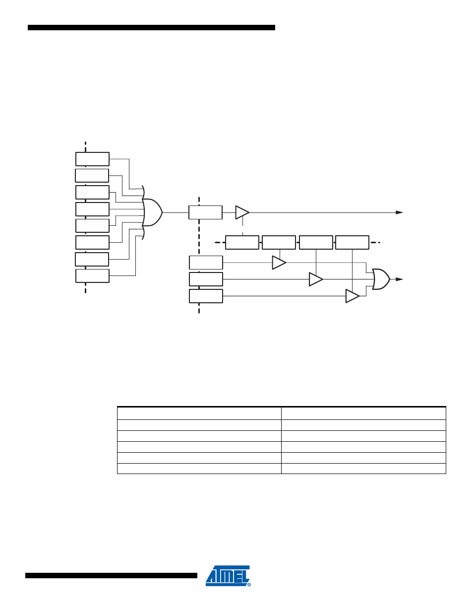
21.5.13
Interrupts
As shown in
, the four communication flags of the LINSIR register are
combined to drive two interrupts. Each of these flags have their respective enable interrupt bit in
LINENIR register.
Section 21.5.8 “xxOK Flags” on page 213
and
Section 21.5.9 “xxERR Flags” on page 214
).
Figure 21-13. LIN Interrupt Mapping
21.5.14
Message Filtering
Message filtering based upon the whole identifier is not implemented. Only a status for frame
headers having 0x3C, 0x3D, 0x3E and 0x3F as identifier is available in the LINSIR register.
The LIN protocol says that a message with an identifier from 60 (0x3C) up to 63 (0x3F) uses a
classic checksum (sum over the data bytes only). Software will be responsible for switching cor-
rectly the LIN13 bit to provide/check this expected checksum (the insertion of the ID field in the
computation of the CRC is set - or not - just after entering the Rx or Tx Response command).
LIDOK
LINSIR.2
LTXOK
LINSIR.1
LRXOK
LINSIR.0
LABORT
LINERR.7
LTOERR
LINERR.6
LOVERR
LINERR.5
LERR
LINSIR.3
LIN IT
LENERR
LFERR
LINERR.4
LSERR
LINERR.3
LPERR
LINERR.2
LCERR
LINERR.1
LBERR
LINERR.0
LIN ERR
LENIDOK
LINENIR.2
LENTXOK
LINENIR.1
LENRXOK
LINENIR.0
LINENIR.3
Table 21-4.
Frame Status
LIDST[2..0]
Frame Status
0xx
b
No specific identifier
100
b
60 (0x3C) identifier
101
b
61 (0x3D) identifier
110
b
62 (0x3E) identifier
111
b
63 (0x3F) identifier