8 linidr – lin identifier register, 9 linsel – lin data buffer selection register, Section 21.6.8 “linidr – lin identifier – Rainbow Electronics ATmega64M1 User Manual
Page 223
223
8209A–AVR–08/09
ATmega16M1/32M1/64M1
• Bits 7:4 - LTXDL[3:0]: LIN Transmit Data Length
In LIN mode, this field gives the number of bytes to be transmitted (clamped to 8 Max).
In UART mode this field is unused.
• Bits 3:0 - LRXDL[3:0]: LIN Receive Data Length
In LIN mode, this field gives the number of bytes to be received (clamped to 8 Max).
In UART mode this field is unused.
21.6.8
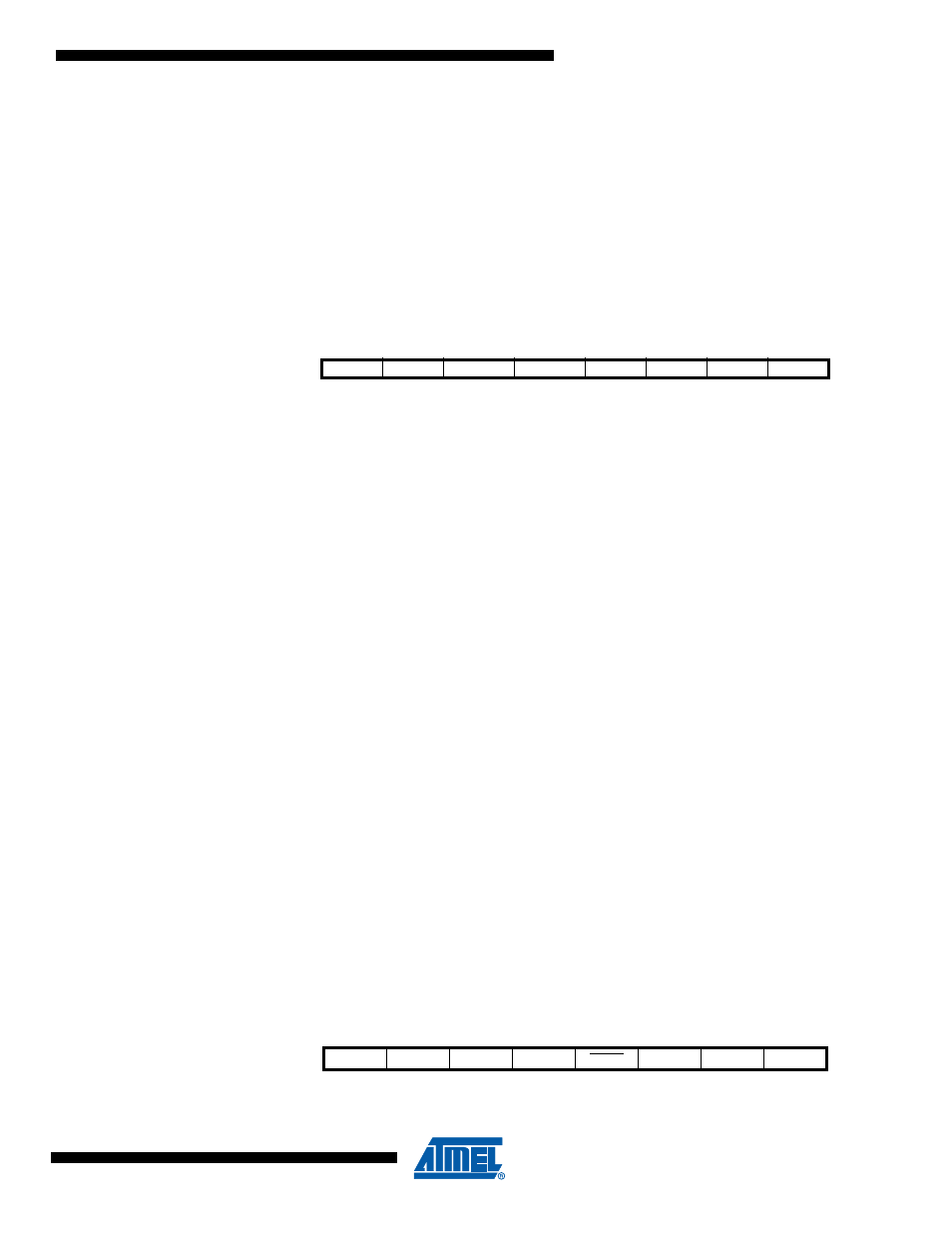
LINIDR – LIN Identifier Register
• Bits 7:6 - LP[1:0]: Parity
In LIN mode:
LP0 = LID4 ^ LID2 ^ LID1 ^ LID0
LP1 = ! ( LID1 ^ LID3 ^ LID4 ^ LID5 )
In UART mode this field is unused.
• Bits 5:4 - LDL[1:0]: LIN 1.3 Data Length
In LIN 1.3 mode:
– 00 = 2-byte response,
– 01 = 2-byte response,
– 10 = 4-byte response,
– 11 = 8-byte response.
In UART mode this field is unused.
• Bits 3:0 - LID[3:0]: LIN 1.3 Identifier
In LIN 1.3 mode: 4-bit identifier.
In UART mode this field is unused.
• Bits 5:0 - LID[5:0]: LIN 2.1 Identifier
In LIN 2.1 mode: 6-bit identifier (no length transported).
In UART mode this field is unused.
21.6.9
LINSEL – LIN Data Buffer Selection Register
Bit
7
6
5
4
3
2
1
0
LP1
LP0
LID5 / LDL1
LID4 / LDL0
LID3
LID2
LID1
LID0
LINIDR
Read/Write
R
R
R/W
R/W
R/W
R/W
R/W
R/W
Initial Value
0
0
0
0
0
0
0
0
Bit
7
6
5
4
3
2
1
0
-
-
-
-
LAINC
LINDX2
LINDX1
LINDX0
LINSEL
Read/Write
-
-
-
-
R/W
R/W
R/W
R/W
Initial Value
-
-
-
-
0
0
0
0