2 signal polarity, 3 input mode operation – Rainbow Electronics ATmega64M1 User Manual
Page 144
144
8209A–AVR–08/09
ATmega16M1/32M1/64M1
outputs. This way needs that CLK
PSC
is running. So thanks to PSC Asynchronous Output Con-
trol bit (PAOCnA/B), PSCINn input can desactivate directly the PSC outputs. Notice that in this
case, input is still taken into account as usually by Input Module System as soon as CLK
PSC
is
running.
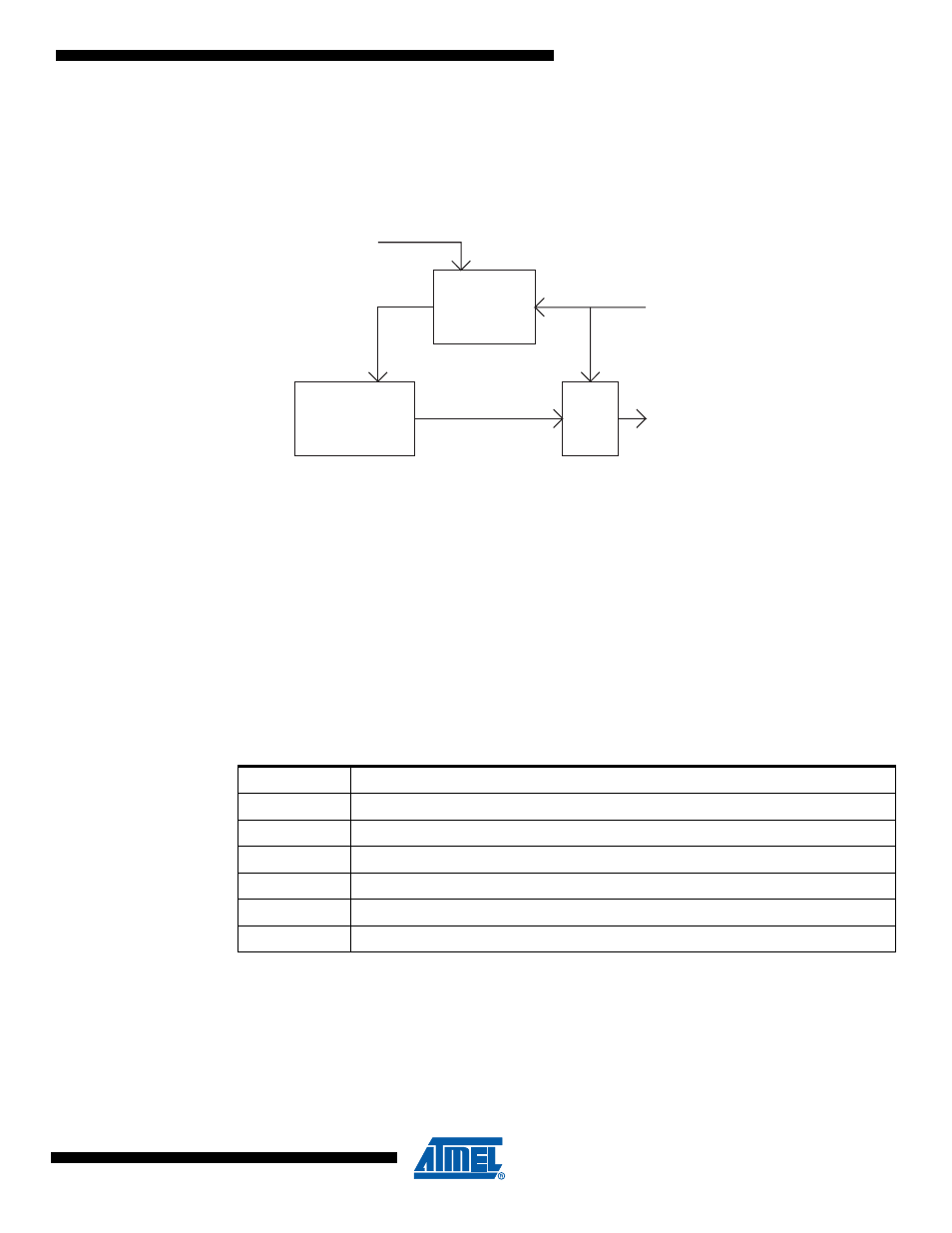
Figure 18-11. PSC Input Filtering
18.9.1.2
Signal Polarity
One can select the active edge (edge modes) or the active level (level modes) See PELEVnx bit
description in Section "PMICn – PSC Module n Input Control Register", page 151.
If PELEVnx bit set, the significant edge of PSCn Input A or B is rising (edge modes) or the active
level is high (level modes) and vice versa for unset/falling/low
- In 2- or 4-ramp mode, PSCn Input A is taken into account only during Dead-Time0 and On-
Time0 period (respectively Dead-Time1 and On-Time1 for PSCn Input B).
- In 1-ramp-mode PSC Input A or PSC Input B act on the whole ramp.
18.9.1.3
Input Mode Operation
Thanks to 4 configuration bits (PRFM3:0), it’s possible to define the mode of the PSC inputs.
Notice: All following examples are given with rising edge or high level active inputs.
Digital
Filter
4 x CLK
PSC Input
Module X
Ouput
Stage
PSCOUTnX
PIN
PSC Module n Input
CLK
PSC
PSC
Table 18-5.
PSC Input Mode Operation
PRFMn2:0
Description
000b
No action, PSC Input is ignored
001b
Disactivate module n Outputs A
010b
Disactivate module n Output B
011b
Disactivate module n Output A & B
10x
Disactivate all PSC Output
11xb
Halt PSC and Wait for Software Action