6 pll, 1 internal pll – Rainbow Electronics ATmega64M1 User Manual
Page 32
32
8209A–AVR–08/09
ATmega16M1/32M1/64M1
9.6
PLL
9.6.1
Internal PLL
The internal PLL in ATmega16M1/32M1/64M1 generates a clock frequency that is 64x multiplied
from nominally 1 MHz input. The source of the 1 MHz PLL input clock is the output of the internal
RC Oscillator which is divided down to 1 MHz. See the
The PLL is locked on the RC Oscillator and adjusting the RC Oscillator via OSCCAL Register
will adjust the fast peripheral clock at the same time. However, even if the possibly divided RC
Oscillator is taken to a higher frequency than 1 MHz, the fast peripheral clock frequency satu-
rates at 70 MHz (worst case) and remains oscillating at the maximum frequency. It should be
noted that the PLL in this case is not locked any more with the RC Oscillator clock.
Therefore it is recommended not to take the OSCCAL adjustments to a higher frequency than 1
MHz in order to keep the PLL in the correct operating range. The internal PLL is enabled only
when the PLLE bit in the register PLLCSR is set. The bit PLOCK from the register PLLCSR is
set when PLL is locked.
Both internal 1 MHz RC Oscillator and PLL are switched off in Power-down and Standby sleep
modes
.
Note:
1. This value do not provide a proper restart ; do not use PD in this clock scheme
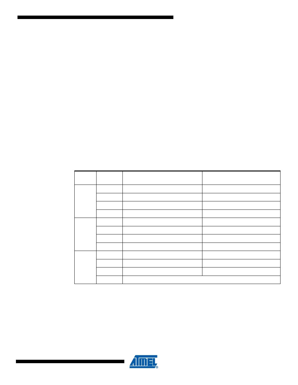
Table 9-7.
Start-up Times when the PLL is selected as system clock
CKSEL
3..0
SUT1..0
Start-up Time from Power-down
and Power-save
Additional Delay from Reset
(V
CC
= 5.0V)
0011
RC Osc
00
1K CK
14CK
01
1K CK
14CK + 4 ms
10
1K CK
14CK + 64 ms
11
16K CK
14CK
0101
Ext Osc
00
1K CK
14CK
01
1K CK
14CK + 4 ms
10
16K CK
14CK + 4 ms
11
16K CK
14CK + 64 ms
0001
Ext Clk
00
14CK
01
14CK + 4 ms
10
14CK + 64 ms
11
Reserved