5 acsr – analog comparator status register, See “acsr – analog com – Rainbow Electronics ATmega64M1 User Manual
Page 262
262
8209A–AVR–08/09
ATmega16M1/32M1/64M1
.
• Bit 3 – Res: Reserved
This bit isreserved and will always read as zero.
• Bit 2:0– AC3M[2:0]: Analog Comparator 3 Multiplexer register
These 3 bits determine the input of the negative input of the analog comparator.
The different setting are shown in
24.4.5
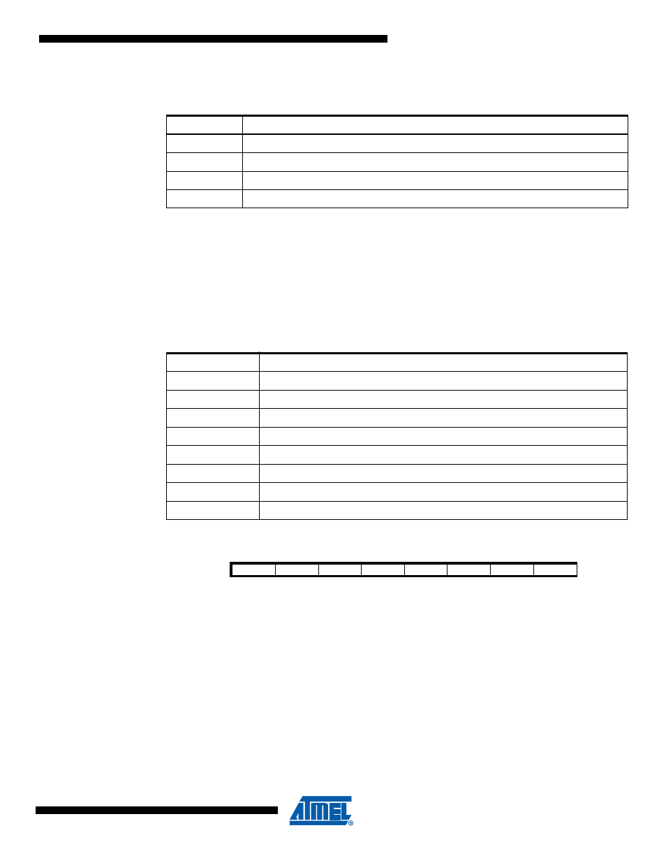
ACSR – Analog Comparator Status Register
• Bit 7 – AC3IF: Analog Comparator 3 Interrupt Flag Bit
This bit is set by hardware when comparator 3 output event triggers off the interrupt mode
defined by AC3IS1 and AC3IS0 bits in AC2CON register.
This bit is cleared by hardware when the corresponding interrupt vector is executed in case the
AC3IE in AC3CON register is set. Anyway, this bit is cleared by writing a logical one on it.
This bit can also be used to synchronize ADC or DAC conversions.
• Bit 6 – AC2IF: Analog Comparator 2 Interrupt Flag Bit
This bit is set by hardware when comparator 2 output event triggers off the interrupt mode
defined by AC2IS1 and AC2IS0 bits in AC2CON register.
This bit is cleared by hardware when the corresponding interrupt vector is executed in case the
Table 24-7.
Interrupt sensitivity selection
AC3IS[1:0]
Description
00
Comparator Interrupt on output toggle
01
Reserved
10
Comparator interrupt on output falling edge
11
Comparator interrupt on output rising edge
Table 24-8.
Analog Comparator 3 negative input selection
AC3M[2:0]
Description
000
“Vref”/6.40
001
“Vref”/3.20
010
“Vref”/2.13
011
“Vref”/1.60
100
Bandgap (1.1V)
101
DAC result
110
Analog Comparator Negative Input (ACMPM pin)
111
Reserved
Bit
7
6
5
4
3
2
1
0
AC3IF
AC2IF
AC1IF
AC0IF
AC3O
AC2O
AC1O
AC0O
ACSR
Read/Write
R/W
R/W
R/W
R/W
R
R
R
R
Initial Value
0
0
0
0
0
0
0
0