5 enable / disable, 6 lin commands, 1 rx header / lin abort function – Rainbow Electronics ATmega64M1 User Manual
Page 205
205
8209A–AVR–08/09
ATmega16M1/32M1/64M1
21.4.5
Enable / Disable
Setting the LENA bit in LINCR register enables the LIN/UART controller. To disable the
LIN/UART controller, LENA bit must be written to 0. No wait states are implemented, so, the dis-
able command is taken into account immediately.
21.4.6
LIN Commands
Clearing the LCMD[2] bit in LINCR register enables LIN commands.
As shown in
, four functions controlled by the LCMD[1..0] bits of LINCR
register are available (c.f.
).
21.4.6.1
Rx Header / LIN Abort Function
This function (or state) is mainly the withdrawal mode of the controller.
When the controller has to execute a master task, this state is the start point before enabling a
Tx Header command.
When the controller has only to execute slave tasks, LIN header detection/acquisition is enabled
as background function. At the end of such an acquisition (Rx Header function), automatically
the appropriate flags are set, and in LIN 1.3, the LINDLR register is set with the uncoded length
value.
This state is also the start point before enabling the Tx or the Rx Response command.
A running function (i.e. Tx Header, Tx or Rx Response) can be aborted by clearing LCMD[1..0]
bits in LINCR register. In this case, an abort flag - LABORT - in LINERR register will be set to
inform the other software tasks. No wait states are implemented, so, the abort command is taken
into account immediately.
• Rx Header function is responsible for:
• The BREAK field detection,
• The hardware re-synchronization analyzing the SYNCH field,
• The reception of the PROTECTED IDENTIFIER field, the parity control and the update of the
LINDLR register in case of LIN 1.3,
• The starting of the Frame_Time_Out,
• The checking of the LIN communication integrity.
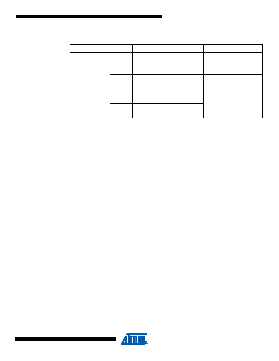
Table 21-1.
LIN/UART Command List
LENA
LCMD[2]
LCMD[1]
LCMD[0]
Command
Comment
0
x
x
x
Disable peripheral
1
0
0
0
Rx Header - LIN abort
LIN withdrawal
1
Tx Header
LCMD[2..0]=000 after Tx
1
0
Rx Response
LCMD[2..0]=000 after Rx
1
Tx Response
LCMD[2..0]=000 after Tx
1
0
0
Byte transfer
no CRC, no Time out
LTXDL=LRXDL=0
(LINDLR: read only register)
1
0
Rx Byte
0
1
Tx Byte
1
1
Full duplex