6 system and reset characteristics, Defin, Will – Rainbow Electronics ATmega64M1 User Manual
Page 313: Up time is given in
313
8209A–AVR–08/09
ATmega16M1/32M1/64M1
29.6
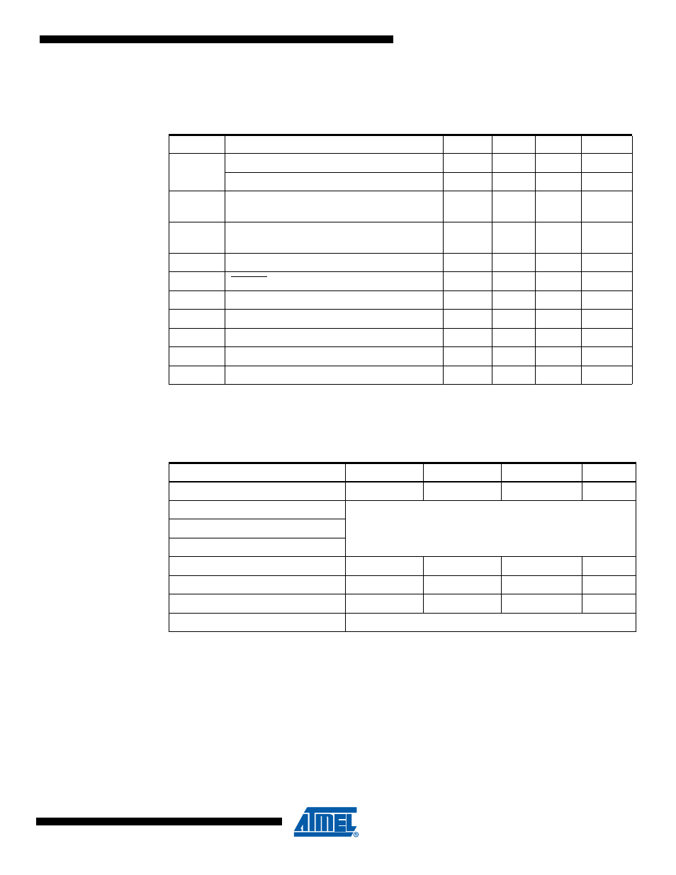
System and Reset Characteristics
Notes:
1. Values are guidelines only
2. Before rising, the supply has to be between
V
PORMIN
and V
PORMAX
to ensure a Reset.
Notes:
1. V
BOT
may be below nominal minimum operating voltage for some devices. For devices where
this is the case, the device is tested down to V
CC
= V
BOT
during the production test. This guar-
antees that a Brown-Out Reset will occur before V
CC
drops to a voltage where correct
operation of the microcontroller is no longer guaranteed. The test is performed using
BODLEVEL = 010 for Low Operating Voltage and BODLEVEL = 101 for High Operating Volt-
age .
2. Values are guidelines only.
Table 29-2.
Reset, Brown-out
and Internal Voltage
Characteristics
Symbol
Parameter
Min
Typ
Max
Units
V
POT
Power-on Reset Threshold Voltage (rising)
1.1
1.4
1.7
V
Power-on Reset Threshold Voltage (falling)
0.8
0.9
1.6
V
V
PORMAX
VCC Max. start voltage to ensure internal
Power-on Reset signal
0.4
V
V
PORMIN
VCC Min. start voltage to ensure internal
Power-on Reset signal
-0.1
V
V
CCRR
VCC Rise Rate to ensure Power-on Reset
0.01
V/ms
V
RST
RESET Pin Threshold Voltage
0.1 V
CC
0.9V
CC
V
V
HYST
Brown-out Detector Hysteresis
50
mV
t
BOD
Min Pulse Width on Brown-out Reset
2
µs
V
BG
Bandgap reference voltage
1.1
V
t
BG
Bandgap reference start-up time
40
µs
I
BG
Bandgap reference current consumption
15
µA
Table 29-3.
BODLEVEL Fuse Coding
BODLEVEL 2..0 Fuses
Min V
BOT
Typ V
BOT
Max V
BOT
Units
111
2.6
110
RESERVED
101
100
011
4.3
V
010
2.7
V
001
4.5
V
000
DISABLED