7 pll characteristics, 8 spi timing characteristics – Rainbow Electronics ATmega64M1 User Manual
Page 314
314
8209A–AVR–08/09
ATmega16M1/32M1/64M1
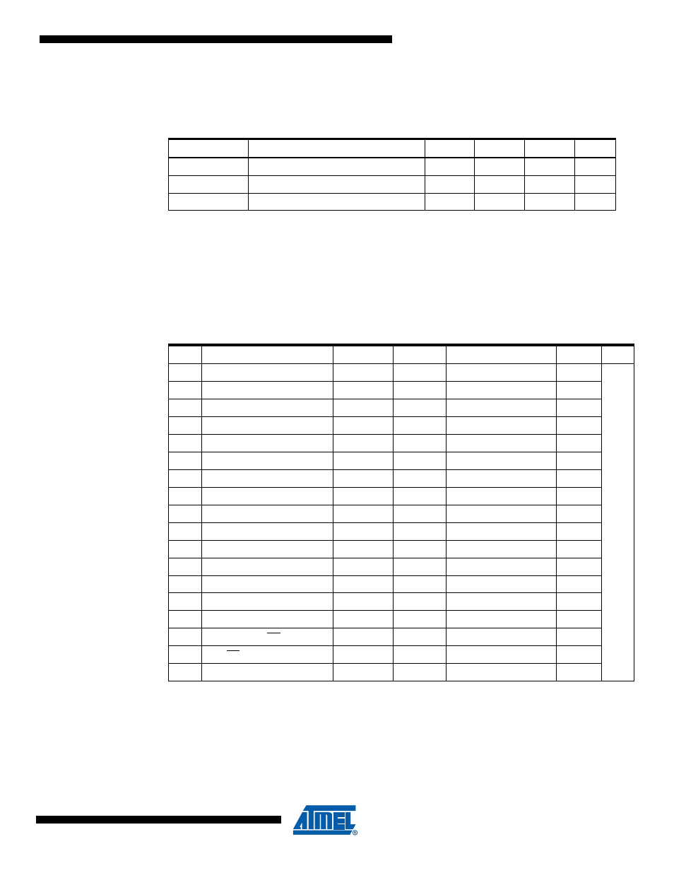
29.7
PLL Characteristics
.
Note:
While connected to external clock or external oscillator, PLL Input Frequency must be selected to
provide outputs with frequency in accordance with driven parts of the circuit (CPU core, PSC...)
29.8
SPI Timing Characteristics
See
and
for details.
Note:
In SPI Programming mode the minimum SCK high/low period is:
- 2 t
CLCL
for f
CK
< 12 MHz
- 3 t
CLCL
for f
CK
>12 MHz
Table 2. PLL Characteristics - V
CC
= 2.7V to 5.5V (unless otherwise noted)
Symbol
Parameter
Min.
Typ.
Max. Units
PLL
IF
Input Frequency
0.5
1
2
MHz
PLL
F
PLL Factor
64
PLL
LT
Lock-in Time
64
µS
Table 3. SPI Timing Parameters
Description
Mode
Min. Typ.
Max.
1
SCK period
Master
See
ns
2
SCK high/low
Master
50% duty cycle
3
Rise/Fall time
Master
3.6
4
Setup
Master
10
5
Hold
Master
10
6
Out to SCK
Master
0.5 • t
sck
7
SCK to out
Master
10
8
SCK to out high
Master
10
9
SS low to out
Slave
15
10
SCK period
Slave
4 • t
ck
11
SCK high/low
(1)
Slave
2 • t
ck
12
Rise/Fall time
Slave
1600
13
Setup
Slave
10
14
Hold
Slave
t
ck
15
SCK to out
Slave
15
16
SCK to SS high
Slave
20
17
SS high to tri-state
Slave
10
18
SS low to SCK
Slave
20