1 power-on reset, Figure 11-1 – Rainbow Electronics ATmega64M1 User Manual
Page 44
44
8209A–AVR–08/09
ATmega16M1/32M1/64M1
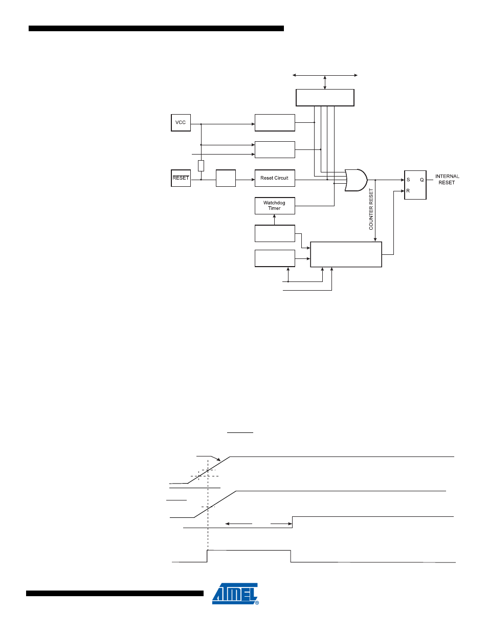
Figure 11-1. Reset Logic
11.2.1
Power-on Reset
A Power-on Reset (POR) pulse is generated by an On-chip detection circuit. The detection level
is defined in
“System and Reset Characteristics” on page 313
. The POR is activated whenever
V
CC
is below the detection level. The POR circuit can be used to trigger the start-up Reset, as
well as to detect a failure in supply voltage.
A Power-on Reset (POR) circuit ensures that the device is reset from Power-on. Reaching the
Power-on Reset threshold voltage invokes the delay counter, which determines how long the
device is kept in RESET after V
CC
rise. The RESET signal is activated again, without any delay,
when V
CC
decreases below the detection level.
Figure 11-2. MCU Start-up, RESET Tied to V
CC
MCU Status
Register (MCUSR)
Brown-out
Reset Circuit
BODLEVEL [2..0]
Delay Counters
CKSEL[3:0]
CK
TIMEOUT
WDRF
BORF
EXTRF
PORF
DATA BUS
Clock
Generator
Spike
Filter
Pull-up Resistor
Watchdog
Oscillator
SUT[1:0]
Power-on Reset
Circuit
RESET
TIME-OUT
INTERNAL
RESET
t
TOUT
V
RST
V
V
CC
CCRR
V
V
PORMIN
PORMAX