4 watchdog timer, 1 features, 2 overview – Rainbow Electronics ATmega64M1 User Manual
Page 47
47
8209A–AVR–08/09
ATmega16M1/32M1/64M1
1.
When the BOD is enabled (by programming the BODLEVEL [2..0] Fuse).
2.
When the bandgap reference is connected to the Analog Comparator (by setting the
ACBG bit in ACSR).
3.
When the ADC is enabled.
4.
When the DAC is enabled.
Thus, when the BOD is not enabled, after setting the ACBG bit or enabling the ADC or the DAC,
the user must always allow the reference to start up before the output from the Analog Compar-
ator or ADC or DAC is used. To reduce power consumption in Power-down mode, the user can
avoid the three conditions above to ensure that the reference is turned off before entering
Power-down mode.
11.4
Watchdog Timer
11.4.1
Features
•
Clocked from separate On-chip Oscillator
•
3 Operating modes
– Interrupt
– System Reset
– Interrupt and System Reset
•
Selectable Time-out period from 16ms to 8s
•
Possible Hardware fuse Watchdog always on (WDTON) for fail-safe mode
11.4.2
Overview
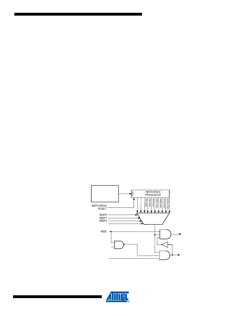
The ATmega16M1/32M1/64M1 has an Enhanced Watchdog Timer (WDT). The WDT is a timer
counting cycles of a separate on-chip 128 kHz oscillator. The WDT gives an interrupt or a sys-
tem reset when the counter reaches a given time-out value. In normal operation mode, it is
required that the system uses the WDR - Watchdog Timer Reset - instruction to restart the coun-
ter before the time-out value is reached. If the system doesn't restart the counter, an interrupt or
system reset will be issued.
Figure 11-7. Watchdog Timer
In Interrupt mode, the WDT gives an interrupt when the timer expires. This interrupt can be used
to wake the device from sleep-modes, and also as a general system timer. One example is to
limit the maximum time allowed for certain operations, giving an interrupt when the operation
has run longer than expected. In System Reset mode, the WDT gives a reset when the timer
128 KHz
OSCILLATOR
MCU RESET
INTERRUPT
WDIE
WDIF
OSC/2K
OSC/4K
OSC/8K
WDP3