10 psc interrupt mask register – pim – Rainbow Electronics ATmega64M1 User Manual
Page 152
152
8209A–AVR–08/09
ATmega16M1/32M1/64M1
• Bit 6 – PISELn: PSC Module n Input Select
Clear this bit to select PSCINn as module n input.
Set this bit to select Comparator n output as module n input.
• Bit 5 – PELEVn: PSC Module n Input Level Selector
When this bit is clear, the low level of selected input generates the significative event for fault
function .
When this bit is set, the high level of selected input generates the significative event for fault
function.
• Bit 4 – PFLTEn: PSC Module n Input Filter Enable
Setting this bit (to one) activates the Input Noise Canceler. When the noise canceler is activated,
the input from the input pin is filtered. The filter function requires four successive equal valued
samples of the input pin for changing its output. The Input is therefore delayed by four oscillator
cycles when the noise canceler is enabled.
• Bit 3 – PAOCn: PSC Module n 0 Asynchronous Output Control
When this bit is clear, Fault input can act directly to PSC module n outputs A & B. See
Section “PSC Input Configuration”, page 143.
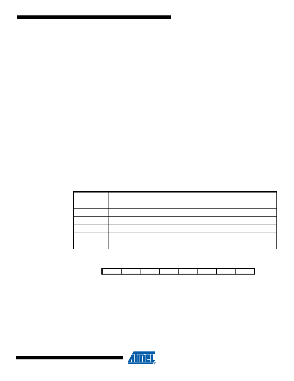
• Bit 2:0 – PRFMn2:0: PSC Module n Input Mode
These three bits define the mode of operation of the PSC inputs.
Table 18-12. Input Mode Operation
18.16.10 PSC Interrupt Mask Register – PIM
• Bit 7:4 – Res: Reserved
These bits are reserved and will always read as zero.
• Bit 3 – PEVE2: PSC External Event 2 Interrupt Enable
When this bit is set, an external event which can generates a a fault on module 2 generates also
an interrupt.
PRFMn2:0
Description
000b
No action, PSC Input is ignored
001b
Disactivate module n Outputs A
010b
Disactivate module n Output B
011b
Disactivate module n Output A & B
10x
Disactivate all PSC Output
11xb
Halt PSC and Wait for Software Action
Bit
7
6
5
4
3
2
1
0
-
-
-
-
PEVE2
PEVE1
PEVE0
PEOPE
PIM
Read/Write
R
R
R
R
R/W
R/W
R/W
R/W
Initial Value
0
0
0
0
0
0
0
0