Power management and sleep modes, 1 overview, 2 sleep modes – Rainbow Electronics ATmega64M1 User Manual
Page 38: 3 idle mode, Power management and
38
8209A–AVR–08/09
ATmega16M1/32M1/64M1
10. Power Management and Sleep Modes
10.1
Overview
Sleep modes enable the application to shut down unused modules in the MCU, thereby saving
power. The AVR provides various sleep modes allowing the user to tailor the power consump-
tion to the application’s requirements.
10.2
Sleep Modes
presents the different clock systems in the ATmega16M1/32M1/64M1,
and their distribution. The figure is helpful in selecting an appropriate sleep mode.
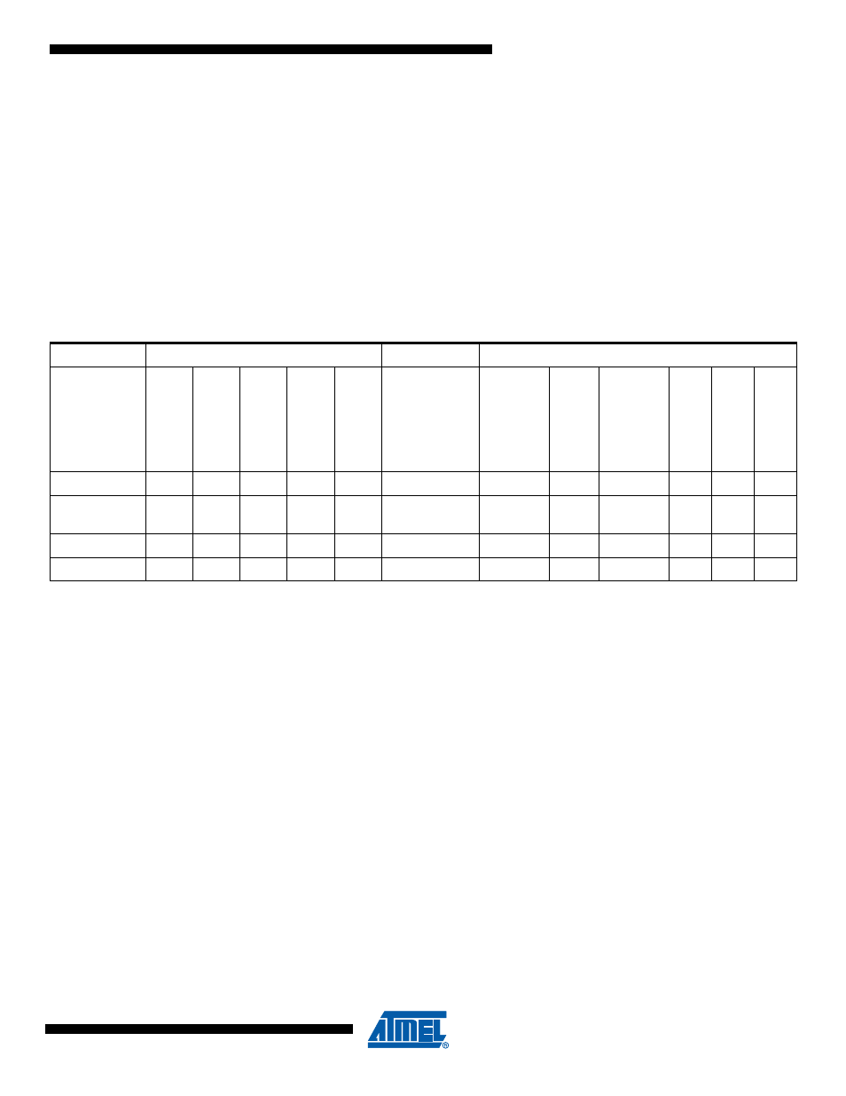
shows the different sleep modes and their wake-up sources.
Notes:
1. Only recommended with external crystal or resonator selected as clock source.
2. Only level interrupt.
To enter any of the five sleep modes, the SE bit in SMCR must be written to logic one and a
SLEEP instruction must be executed. The SM2, SM1, and SM0 bits in the SMCR Register select
which sleep mode (Idle, ADC Noise Reduction, Power-down, Power-save, or Standby) will be
activated by the SLEEP instruction. See
for a summary.
If an enabled interrupt occurs while the MCU is in a sleep mode, the MCU wakes up. The MCU
is then halted for four cycles in addition to the start-up time, executes the interrupt routine, and
resumes execution from the instruction following SLEEP. The contents of the register file and
SRAM are unaltered when the device wakes up from sleep. If a reset occurs during sleep mode,
the MCU wakes up and executes from the Reset Vector.
10.3
Idle Mode
When the SM2:0 bits are written to 000, the SLEEP instruction makes the MCU enter Idle mode,
stopping the CPU but allowing SPI, UART, Analog Comparator, ADC, Timer/Counters, Watch-
dog, and the interrupt system to continue operating. This sleep mode basically halt clk
CPU
and
clk
FLASH
, while allowing the other clocks to run.
Idle mode enables the MCU to wake up from external triggered interrupts as well as internal
ones like the Timer Overflow and UART Transmit Complete interrupts. If wake-up from the Ana-
log Comparator interrupt is not required, the Analog Comparator can be powered down by
Table 10-1.
Active Clock Domains and Wake-up Sources in the Different Sleep Modes.
Active Clock Domains
Oscillators
Wake-up Sources
Sleep Mode
clk
CPU
clk
FLASH
clk
IO
clk
ADC
clk
PL
L
Ma
in
Cl
o
c
k
Source Enab
led
INT3..
0
PSC
SPM
/EEPR
OM
Read
y
ADC
WDT
O
ther
I/O
Idle
X
X
X
X
X
X
X
X
X
X
ADC Noise
Reduction
X
X
X
X
X
X
X
Power-down
X
Standby
X
X