5 register description, 1 mcucr – mcu control register, Figure – Rainbow Electronics ATmega64M1 User Manual
Page 160: Figure 19-4
160
8209A–AVR–08/09
ATmega16M1/32M1/64M1
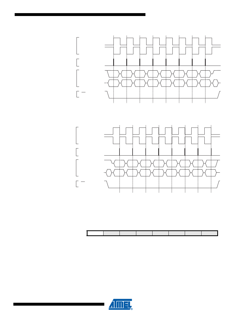
Figure 19-3. SPI Transfer Format with CPHA = 0
Figure 19-4. SPI Transfer Format with CPHA = 1
19.5
Register Description
19.5.1
MCUCR – MCU Control Register
Bit 7– SPIPS: SPI Pin Redirection
Thanks to SPIPS (SPI Pin Select) in MCUCR Sfr, SPI pins can be redirected.
• When the SPIPS bit is written to zero, the SPI signals are directed on pins MISO,MOSI, SCK
and SS.
• When the SPIPS bit is written to one,the SPI signals are directed on alternate SPI pins,
MISO_A, MOSI_A, SCK_A and SS_A.
Note that programming port are always located on alternate SPI port.
Bit 1
Bit 6
LSB
MSB
SCK (CPOL = 0)
mode 0
SAMPLE I
MOSI/MISO
CHANGE 0
MOSI PIN
CHANGE 0
MISO PIN
SCK (CPOL = 1)
mode 2
SS
MSB
LSB
Bit 6
Bit 1
Bit 5
Bit 2
Bit 4
Bit 3
Bit 3
Bit 4
Bit 2
Bit 5
MSB first (DORD = 0)
LSB first (DORD = 1)
SCK (CPOL = 0)
mode 1
SAMPLE I
MOSI/MISO
CHANGE 0
MOSI PIN
CHANGE 0
MISO PIN
SCK (CPOL = 1)
mode 3
SS
MSB
LSB
Bit 6
Bit 1
Bit 5
Bit 2
Bit 4
Bit 3
Bit 3
Bit 4
Bit 2
Bit 5
Bit 1
Bit 6
LSB
MSB
MSB first (DORD = 0)
LSB first (DORD = 1)
Bit
7
6
5
4
3
2
1
0
SPIPS
–
–
PUD
–
–
IVSEL
IVCE
MCUCR
Read/Write
R/W
R
R
R/W
R
R
R/W
R/W
Initial Value
0
0
0
0
0
0
0
0