9 psc input, 1 psc input configuration, 1 filter enable – Rainbow Electronics ATmega64M1 User Manual
Page 143
143
8209A–AVR–08/09
ATmega16M1/32M1/64M1
Table 18-4.
Internal Outputs
Note:
1.
See “Analog Synchronization” on page 146.
18.9
PSC Input
For detailed information on the PSC, please refer to Application Note ‘AVR138: PSC Cookbook’,
available on the Atmel web site.
Each module 0, 1 and 2 of PSC has its own system to take into account one PSC input. Accord-
ing to PSC Module n Input Control Register (
See “PMICn – PSC Module n Input Control
), PSCINn input can act has a Retrigger or Fault input.
Each block A or B is also configured by this PSC Module n Input Control Register (PMICn).
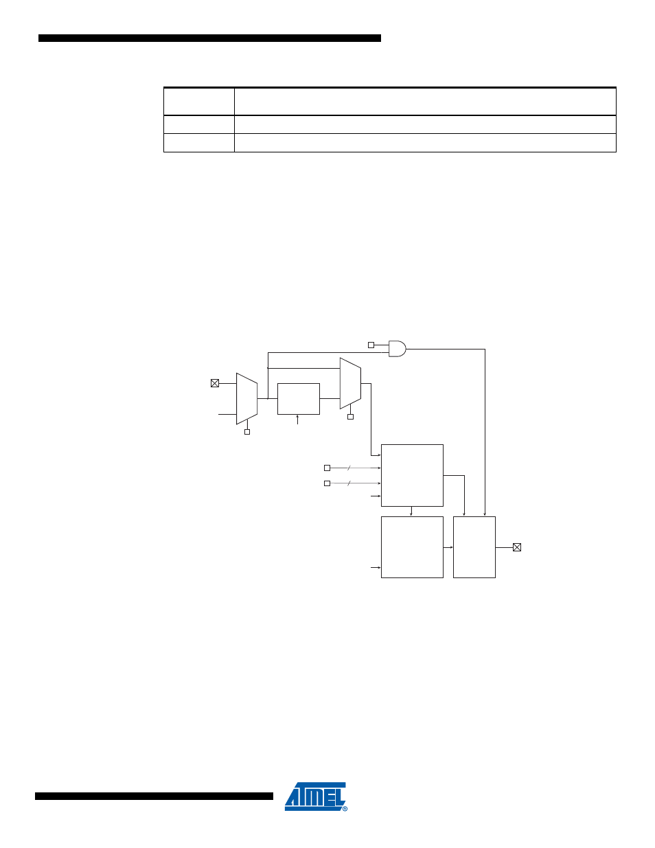
Figure 18-10. PSC Input Module
18.9.1
PSC Input Configuration
The PSC Input Configuration is done by programming bits in configuration registers.
18.9.1.1
Filter Enable
If the “Filter Enable” bit is set, a digital filter of 4 cycles is inserted before evaluation of the signal.
The disable of this function is mainly needed for prescaled PSC clock sources, where the noise
cancellation gives too high latency.
Important: If the digital filter is active, the level sensitivity is true also with a disturbed PSC clock
to deactivate the outputs (emergency protection of external component). Likewise when used as
fault input, PSC Module n Input A or Input B have to go through PSC to act on PSCOUTn0/1/2
Name
Description
Type
Width
IRQPSCn
PSC Interrupt Request : two souces, overflow, fault
Signal
PSCASY
ADC Synchronization (+ Amplifier Syncho. )
(1)
Signal
Analog
Comparator
n Output
PSCINn
Digital
Filter
PISELnA
(PISELnB)
PFLTEnA
(PFLTEnB)
PAOCnA
(PAOCnB)
Input
Processing
(retriggering ...)
MPSC Core
(Counter,
Waveform
Generator, ...)
Control
of the
6 outputs
1
0
0
1
PSCOUTnA
PSCOUTnB
CLK
PSC
CLK
PSC
CLK
PSC
PELEVnA /
(PELEVnB)
PRFMnA3:0
(PRFMnB3:0)
PCAEnA
(PCAEnB)
2
4