4 link aggregation, Figure 81 switch configuration: stp conf, Table 55 switch configuration: stp conf – ZyXEL Communications NetAtlas Workgroup User Manual
Page 124
NetAtlas Workgroup Ethernet Switch Manager User’s Guide
Chapter 14 Switch Configuration
124
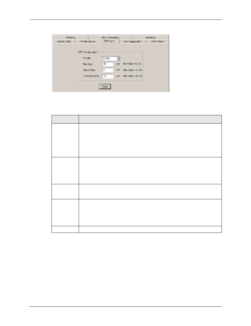
Figure 81 Switch Configuration: STP Conf.
The following table describes the labels in this screen.
14.4 Link Aggregation
Link aggregation (trunking) is the grouping of physical ports into one logical higher-capacity
link. You may want to trunk ports if for example, it is cheaper to use multiple lower-speed
links than to under-utilize a high-speed, but more costly, single-port link.
However, the more ports you aggregate then the fewer available ports you have. A link
aggregation group is one logical link containing multiple ports.
Table 55 Switch Configuration: STP Conf.
LABEL
DESCRIPTION
Priority
Priority is used in determining the root device, root port and designated port. The
device with the highest priority (lowest numeric value) becomes the RSTP root device.
If all devices have the same priority, the device with the lowest MAC address will then
become the root device. The allowed range is 0 to 65535 (32768 is the default).
The lower the numeric value you assign, the higher the priority for this bridge.
Priority determines the root bridge, which in turn determines Hello Time, Max Age
and Forward Delay.
Max Age
This is the maximum time (in seconds) a device can wait without receiving a BPDU
before attempting to reconfigure. All device ports (except for designated ports) should
receive BPDUs at regular intervals. Any port that ages out STP information (provided
in the last BPDU) becomes the designated port for the attached LAN. If it is a root port,
a new root port is selected from among the device ports attached to the network. The
allowed range is 6 to 40 seconds (20 is the default).
Hello Time
This is the time interval in seconds between BPDU (Bridge Protocol Data Units)
configuration message generations (by all devices in RSTP or the root device in STP).
The allowed range is 1 to 10 seconds (2 is the default).
Forward Delay This is the maximum time (in seconds) a device will wait before changing states. This
delay is required because every device must receive information about topology
changes before it starts to forward frames. In addition, each port needs time to listen
for conflicting information that would make it return to a blocking state; otherwise,
temporary data loops might result. The allowed range is 4 to 30 seconds (15 is the
default).
Apply
Click Apply to save your changes back to the switch.