Toshiba VF-FS1 User Manual
Page 199
E6581381
I-3
9
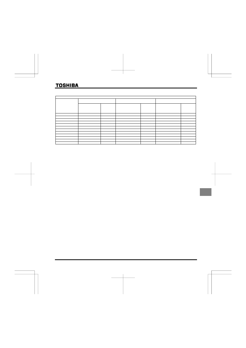
Three-phase 400V class
Combination of inverter and filter
Transmission noise
EN61800-3, 1st Environment, C2
Transmission noise
EN61800-3, 1st Environment, C1
Transmission noise
EN61800-3, 2nd Environment, C3
Inverter
Applicable filters
Length of
motor
connecting
cable (m)
Applicable filters
Length of
motor
connecting
cable (m)
Applicable filters
Length of
motor
connecting
cable (m)
VFFS1-4004PL
With a built-in filter
5
EMFS11-4015BZ
20
EMFS11-4015BZ
50
VFFS1-4007PL
With a built-in filter
5
EMFS11-4015BZ
20
EMFS11-4015BZ
50
VFFS1-4015PL
With a built-in filter
5
EMFS11-4015BZ
20
EMFS11-4015BZ
50
VFFS1-4022PL
With a built-in filter
5
EMFS11-4015BZ
20
EMFS11-4015BZ
50
VFFS1-4037PL
With a built-in filter
5
EMFS11-4025CZ
20
EMFS11-4025CZ
50
VFFS1-4055PL
With a built-in filter
5
EMFS11-4025CZ
20
EMFS11-4025CZ
50
VFFS1-4075PL
With a built-in filter
5
EMFS11-4047DZ
20
EMFS11-4047DZ
50
VFFS1-4110PL
With a built-in filter
5
EMFS11-4047DZ
20
EMFS11-4047DZ
50
VFFS1-4150PL
With a built-in filter
5
EMFS11-4049EZ
20
EMFS11-4049EZ
50
VFFS1-4185PL
With a built-in filter
5
EMFS11-4049EZ
20
EMFS11-4049EZ
50
VFFS1-4220PL
With a built-in filter
50
EMF3-4090F
100
EMF3-4090F
100
VFFS1-4300PL
With a built-in filter
50
EMF3-4092G
100
EMF3-4092G
100
(2)
Use shielded power cables, such as inverter output cables, and shielded control cables. Route the cables
and wires so as to minimize their lengths. Keep a distance between the power cable and the control cable
and between the input and output wires of the power cable. Do not route them in parallel or bind them
together, instead cross at right angle.
(3)
Install the inverter and the filter on the same metal plate. It is more effective in limiting the radiation noise to
install the inverter in a sealed steel cabinet. Using wires as thick and short as possible, earth the metal plate
and the control panel securely with a distance kept between the earth cable and the power cable.
(4)
Route the EMI filter input and output wires apart from each other.
(5)
To suppress radiation noise from cables, ground all shielded cables through a noise cut plate.
It is effective to earth shielded cables in the vicinity of the inverter, cabinet and filter (within a radius of 10cm
from each of them). Inserting a ferrite core in a shielded cable is even more effective in limiting the radiation
noise.
(6)
To further limit the radiation noise, insert a zero-phase reactor in the inverter output line and insert ferrite
cores in the earth cables of the metal plate and cabinet.