Toshiba VF-FS1 User Manual
Page 189
E6581381
H-3
8
(Continued)
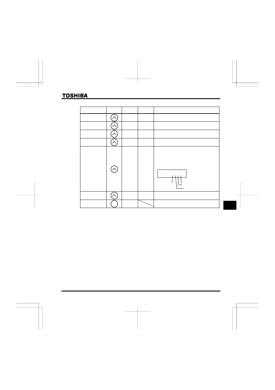
Item displayed
Key
operated
LED
display
Communic
ation No.
Description
Past trip 1
QE
⇔
FE10
Past trip 1 (displayed alternately)
Past trip 2
QJ
⇔
FE11
Past trip 2 (displayed alternately)
Past trip 3
QR
⇔
FE12
Past trip 3 (displayed alternately)
Past trip 4
PGTT
⇔
FE13
Past trip 4 (displayed alternately)
Parts replacement
alarm information
O___K
FE79
The ON/OFF status of each of the cooling fan,
circuit board capacitor, main circuit capacitor of
parts replacement alarm or cumulative operation
time are displayed in bits.
ON:
OFF: _
Cumulative
operation time
V
FE14
The cumulative operation time is displayed.
(0.01=1 hour, 1.00=100 hours)
Default display
mode
The operation frequency is displayed (Operation at
60Hz).
Note 6
Note 7
Note 8
Note 6
Note 6
Note 6
operation
O
___K
Cooling fan
Cumulative
time
Control circuit board capacitor
Main circuit capacitor
MODE
- Power Inverter (15 pages)
- 1800 (6 pages)
- TOSVERT VF-S11 (68 pages)
- Uninterruptible Power System G9000 (104 pages)
- Density (Consistency) Meter LQ500 (9 pages)
- MBSB80-225-43 (1 page)
- TOSNIC-7000S (53 pages)
- 1600EP Series (3 pages)
- 1500 (32 pages)
- TOSVERT VF-FS1 Series (16 pages)
- 4200FA XT1 (1 page)
- G3 Plus Pack (4 pages)
- Tosvert VF-A5 (149 pages)
- 1600 Series (3 pages)
- G9000 (100 pages)
- TEC EO1-33030 (54 pages)
- 1000 Series (2 pages)
- 1500 Plus (31 pages)
- G8000MM (6 pages)
- VT130G1 (99 pages)
- 4200FA Series (2 pages)
- VF-PS1 (10 pages)
- GX7 Series (6 pages)
- 4200FA XT (1 page)
- RMTI-EMD-HT (2 pages)
- W7 Series (6 pages)
- HX7 (6 pages)
- PDP002Z (18 pages)
- RELIABILITY IN MOTION 1700 (39 pages)
- 1700 Series (2 pages)
- G3 TOSVERT-130 (62 pages)
- B-852-TS12-QP (55 pages)
- 1000 (4 pages)
- E3 (7 pages)
- Adjustable Speed Drive H3 (122 pages)
- 55611-001 (2 pages)
- Black Gold Series (2 pages)
- Dura-Bull TX (6 pages)
- Current Relay RC803A-HP1 (19 pages)
- 1800 SERIES (2 pages)
- Isolated-Redundant UPS System (2 pages)
- Tosvert VF-AS1 (312 pages)
- RELIABILITY IN MOTION 1000 (54 pages)
- REMOTE-D (2 pages)
- 15-80KVA (2 pages)