21 communication function (common serial), 1 setting of common function – Toshiba VF-FS1 User Manual
Page 174
E6581381
F-78
6
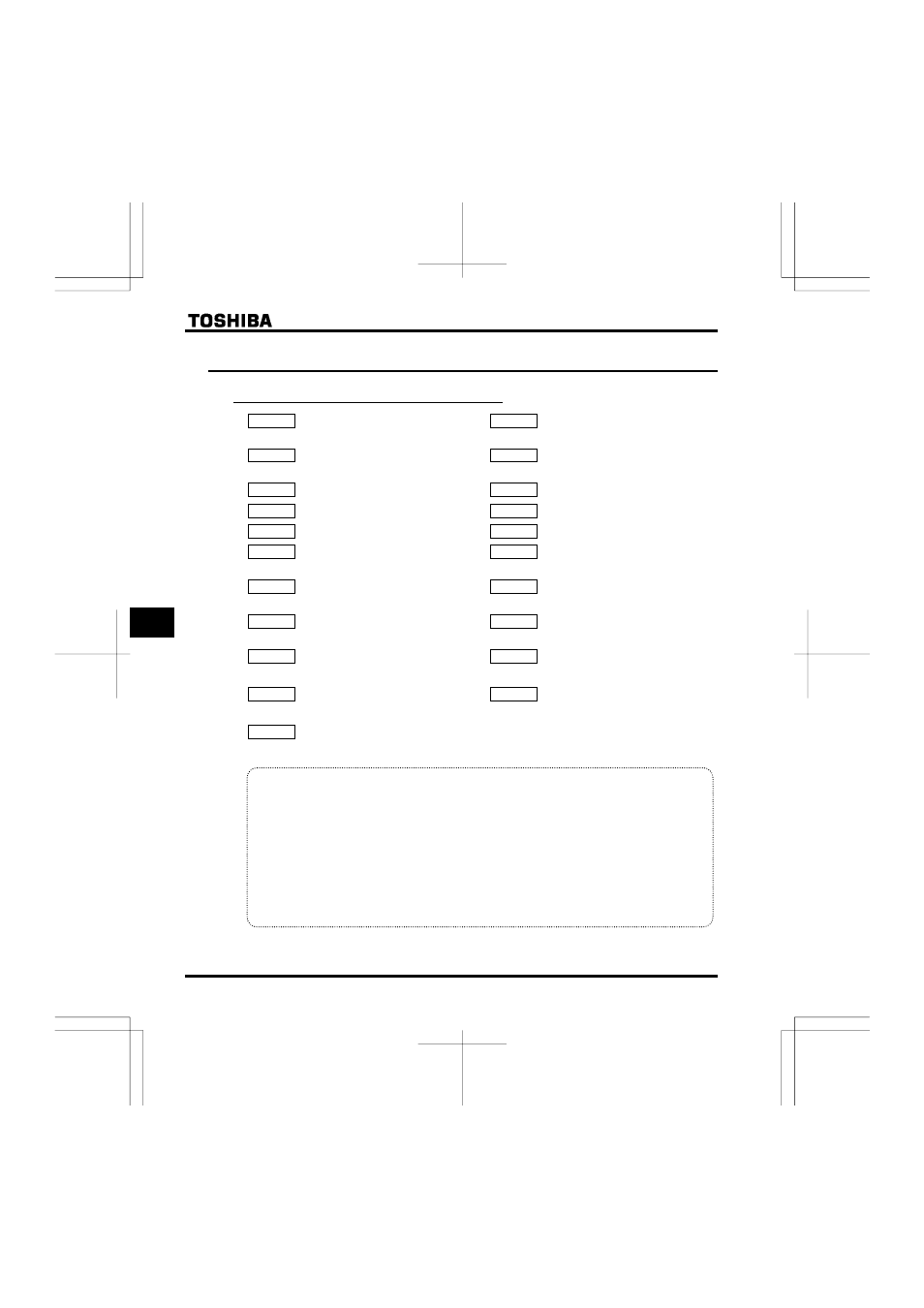
6.21 Communication function (Common serial)
6.21.1 Setting of common function
H
: Communication rate
H
: Operation at communication
error by disconnection
H
: Parity
H
: Number of motor poles for
communication
H
: Inverter number
H
: Block write data 1
H
: Communication error trip time
H
: Block write data 2
H
: Communication waiting time
H
: Block read data 1
H
: Setting of master and slave for
communication between inverters
H
: Block read data 2
H
: Communication commmand point
1 setting
H
: Block read data 3
H
: Communication commmand point
1 frequency
H
: Block read data 4
H
: Communication commmand point
2 setting
H
: Block read data 5
H
: Communication commmand point
2 frequency
H
: Free notes
H
: Selection of communication
protocol
• Function
Function The VF-FS1 Series allows a data communication network to be constructed for exchanging
data between a host computer or controller (referred to collectively as the computer) and the inverter by
connecting an internal RS485 communication function or optional USB communication conversion unit.
The following functions are enabled by data communication between the computer and inverter
(1) Monitoring inverter status (such as the output frequency, current, and voltage)
(2) Sending RUN, STOP and other control commands to the inverter
(3) Reading, editing and writing inverter parameter settings
Data can be exchanged between one computer and one inverter.
Data can be exchanged between the computer and each of the inverters connected.