Toshiba VF-FS1 User Manual
Page 115
E6581381
F-19
6
<
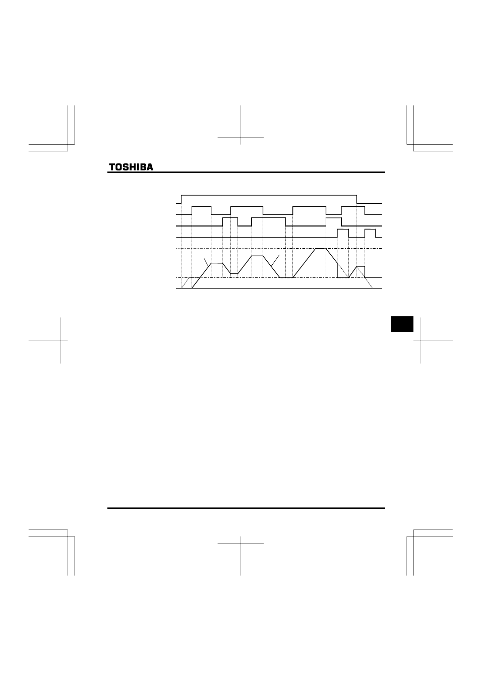
The dotted line denotes the output frequency obtained by combining the slowdown speed and the panel
frequency adjustment speed.
Frequency 0 Hz
Lower limit frequency
Gradient H H
Gradient H H
Upper limit frequency
Decrementing (DOWN) signal
Incrementing (UP) signal
RUN command
Set frequency clearing signal
Note: If the operation frequency is set to the lower limit frequency, it will increase from 0Hz when power is
turned on for the first time after the setting, and therefore the output frequency will not rise until the
operation frequency reaches the lower limit frequency. (Operation at the lower limit frequency)
In this case, the time required for the operation frequency to reach the lower limit frequency can be
shortened by setting HE to the lower limit frequency.
■
Adjustment with pulse signals (Parameter-setting example 2)
Set parameters as follows to adjust the frequency in steps of one pulse:
H
, H ≤ Pulse On time
H
, H = Frequency obtained with each pulse
* The inverter does not respond to any pulses with an ON time shorter than that set with H or
H
. 12ms or more of clearing signal is allowed.