Figure 122 coordinated dialing plan (cdp) – Nortel Networks NN43001-314 User Manual
Page 384
384
Appendix C On-net dialing plan configuration examples
Figure 120
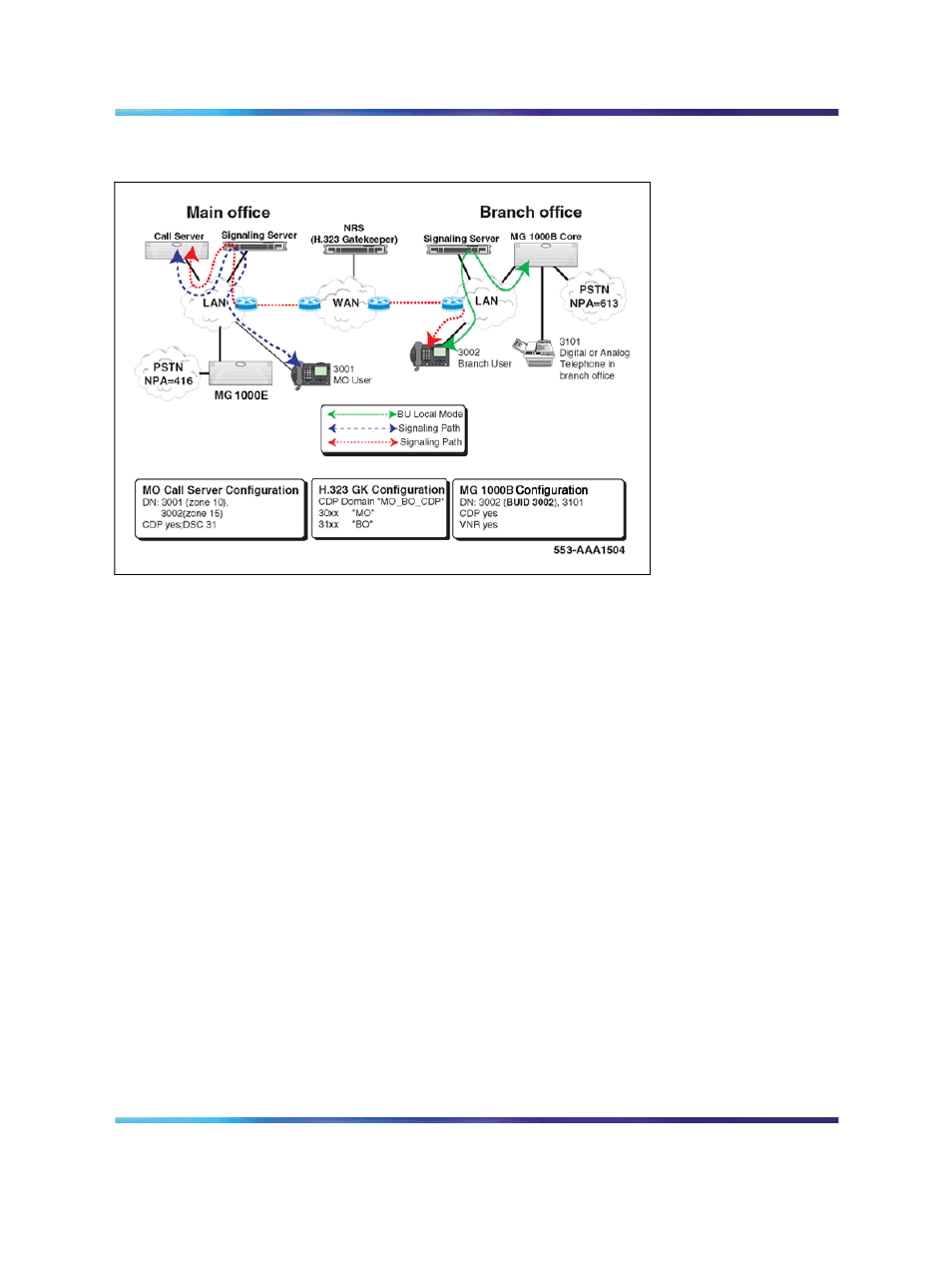
Coordinated Dialing Plan (CDP)
Call Scenarios
This section describes the following call scenarios, all based on
"Coordinated Dialing Plan (CDP)" (page 384)
•
"From main office to Branch Office" (page 384)
•
"From Branch Office to main office" (page 385)
•
"When the Branch User telephone is in Local Mode" (page 385)
From main office to Branch Office
In this scenario, the following occurs:
•
DN 3001 (in the main office) or 3002 (in the Branch Office) dials DN
3101 (a TDM telephone in the MG 1000B).
•
The main office Call Server recognizes the first two digits "31" as a CDP
DSC. It accesses the RLI appropriate for that steering code and uses
the Virtual Trunk specified for that route.
•
The NRS is queried for a destination node IP address with which to
route the call over the Virtual Trunk. Because "31" is registered with the
Branch Office, the Branch Office node IP address is returned.
•
The MG 1000B Core terminates the incoming Virtual Trunk call to DN
3101.
•
The Voice Gateway channel in the Branch Office provides IP-TDM
transcoding.
Nortel Communication Server 1000
Branch Office Installation and Commissioning
NN43001-314
01.02
Standard
Release 5.0
20 June 2007
Copyright © 2007, Nortel Networks
.