Port-based vlan configuration example, Network requirements, Network diagram – H3C Technologies H3C S3100 Series Switches User Manual
Page 97: Configuration procedure

2-6
Port-Based VLAN Configuration Example
Network requirements
z
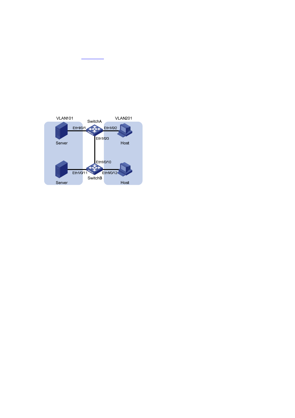
As shown in
, Switch A and Switch B each connect to a server and a workstation (Host).
z
For data security concerns, the two servers are assigned to VLAN 101 with the descriptive string
being “DMZ”, and the PCs are assigned to VLAN 201.
z
The devices within each VLAN can communicate with each other but that in different VLANs
cannot communicate with each other directly.
Network diagram
Figure 2-1 Network diagram for VLAN configuration
Configuration procedure
z
Configure Switch A.
# Create VLAN 101, specify its descriptive string as “DMZ”, and add Ethernet1/0/1 to VLAN 101.
[SwitchA] vlan 101
[SwitchA-vlan101] description DMZ
[SwitchA-vlan101] port Ethernet 1/0/1
[SwitchA-vlan101] quit
# Create VLAN 201, and add Ethernet1/0/2 to VLAN 201.
[SwitchA] vlan 201
[SwitchA-vlan201] port Ethernet 1/0/2
[SwitchA-vlan201] quit
z
Configure Switch B.
# Create VLAN 101, specify its descriptive string as “DMZ”, and add Ethernet1/0/11 to VLAN 101.
[SwitchB] vlan 101
[SwitchB-vlan101] description DMZ
[SwitchB-vlan101] port Ethernet 1/0/11
[SwitchB-vlan101] quit
# Create VLAN 201, and add Ethernet1/0/12 to VLAN 201.
[SwitchB] vlan 201
[SwitchB-vlan201] port Ethernet 1/0/12
[SwitchB-vlan201] quit
z
Configure the link between Switch A and Switch B.
