Advanced acl configuration example, Network requirements, Network diagram – H3C Technologies H3C S3100 Series Switches User Manual
Page 574: Configuration procedure, Layer 2 acl configuration example
1-17
Advanced ACL Configuration Example
Network requirements
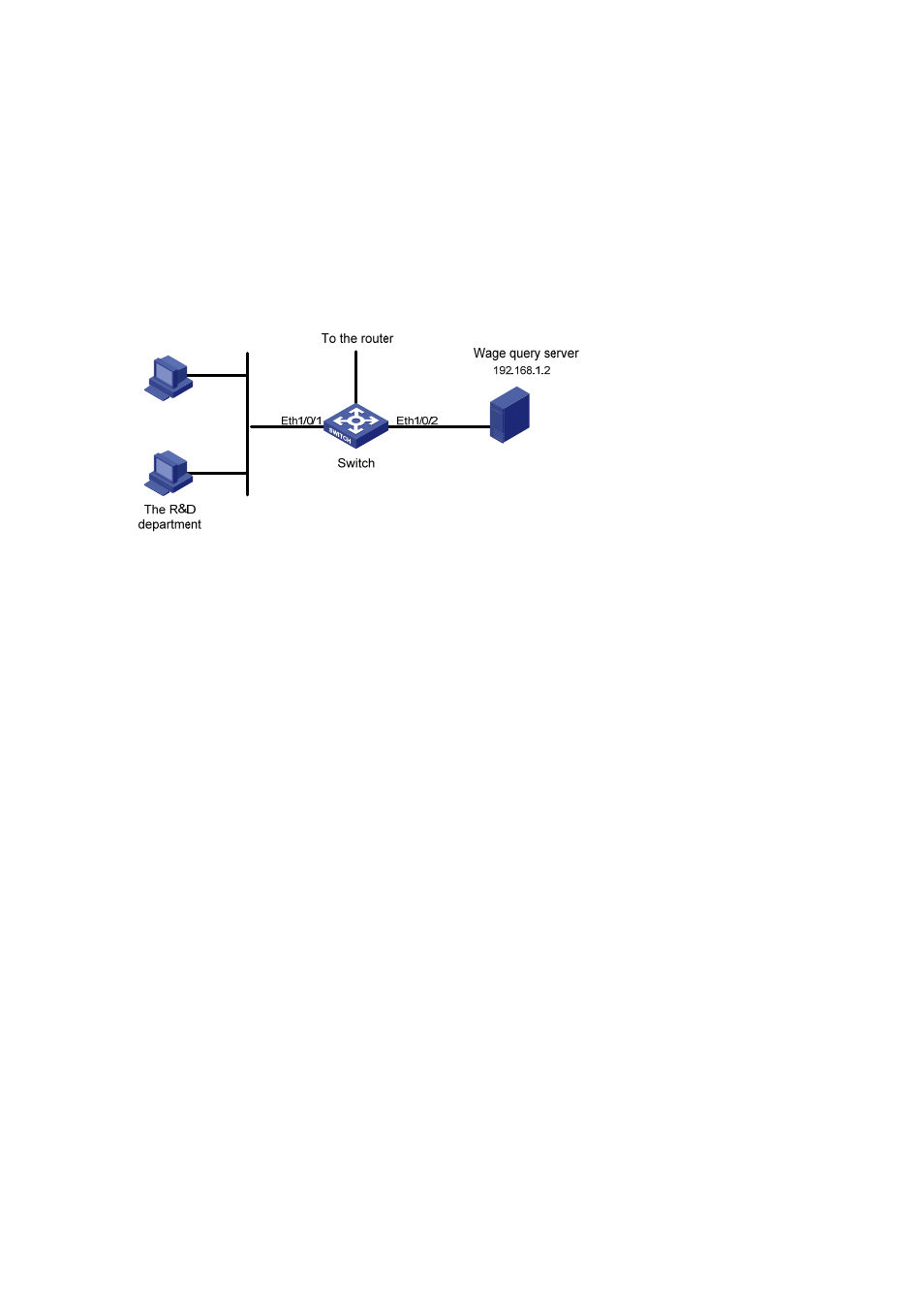
Different departments of an enterprise are interconnected through a switch. The IP address of the wage
query server is 192.168.1.2. The R&D department is connected to Ethernet 1/0/1 of the switch. Apply an
ACL to deny requests from the R&D department and destined for the wage server during the working
hours (8:00 to 18:00).
Network diagram
Figure 1-4 Network diagram for advanced ACL configuration
Configuration procedure
# Define a periodic time range that is active from 8:00 to 18:00 everyday.
[Sysname] time-range test 8:00 to 18:00 working-day
# Define ACL 3000 to filter packets destined for wage query server.
[Sysname] acl number 3000
[Sysname-acl-adv-3000] rule 1 deny ip destination 192.168.1.2 0 time-range test
[Sysname-acl-adv-3000] quit
# Apply ACL 3000 on Ethernet 1/0/1.
[Sysname] interface Ethernet1/0/1
[Sysname-Ethernet1/0/1] packet-filter inbound ip-group 3000
Layer 2 ACL Configuration Example
Network requirements
PC 1 and PC 2 connect to the switch through Ethernet 1/0/1. PC1’s MAC address is 0011-0011-0011.
Apply an ACL to filter packets with the source MAC address of 0011-0011-0011 and the destination
MAC address of 0011-0011-0012 from 8:00 to 18:00 everyday.