Configuration procedure – H3C Technologies H3C S3100 Series Switches User Manual
Page 1050
1-12
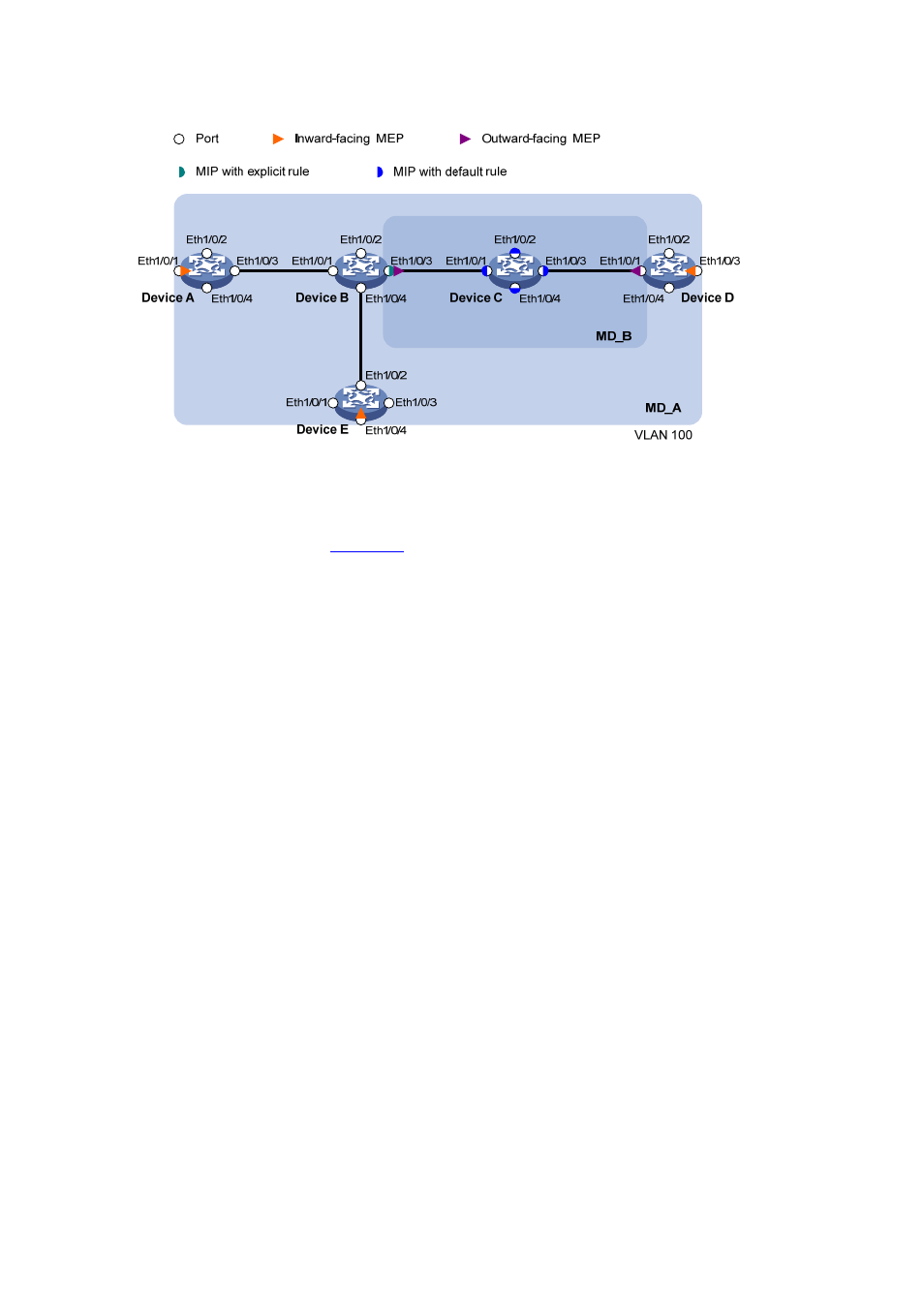
Figure 1-6 Network diagram for CFD configuration
Configuration procedure
1) Configure a VLAN and assign ports to it
On each device shown in
, create VLAN 100 and assign ports Ethernet 1/0/1 through
Ethernet 1/0/4 to VLAN 100.
2) Enable
CFD
# Enable CFD on Device A.
[DeviceA] cfd enable
Enable CFD on Device B through Device E using the same method.
3) Configure service instances
# Create MD_A (level 5) on Device A, create MA_A, which serves VLAN 100, in MD_A, and create
service instance 1 for MD_A and MA_A.
[DeviceA] cfd md MD_A level 5
[DeviceA] cfd ma MA_A md MD_A vlan 100
[DeviceA] cfd service-instance 1 md MD_A ma MA_A
Configure Device E as you configure Device A.
# Create MD_A (level 5) on Device B, create MA_A, which serves VLAN 100, in MD_A, and then create
service instance 1 for MD_A and MA_A; in addition, create MD_B (level 3), create MA_B, which serves
VLAN 100, in MD_B, and then create service instance 2 for MD_B and MA_B.
[DeviceB] cfd md MD_A level 5
[DeviceB] cfd ma MA_A md MD_A vlan 100
[DeviceB] cfd service-instance 1 md MD_A ma MA_A
[DeviceB] cfd md MD_B level 3
[DeviceB] cfd ma MA_B md MD_B vlan 100
[DeviceB] cfd service-instance 2 md MD_B ma MA_B
Configure Device D as you configure Device B.
# Create MD_B (level 3) on Device C, create MA_B, which serves VLAN 100, in MD_B, and then create
service instance 2 for MD_B and MA_B;
[DeviceC] cfd md MD_B level 3
[DeviceC] cfd ma MA_B md MD_B vlan 100