Network diagram, Configuration procedure – H3C Technologies H3C S3100 Series Switches User Manual
Page 531
2-30
z
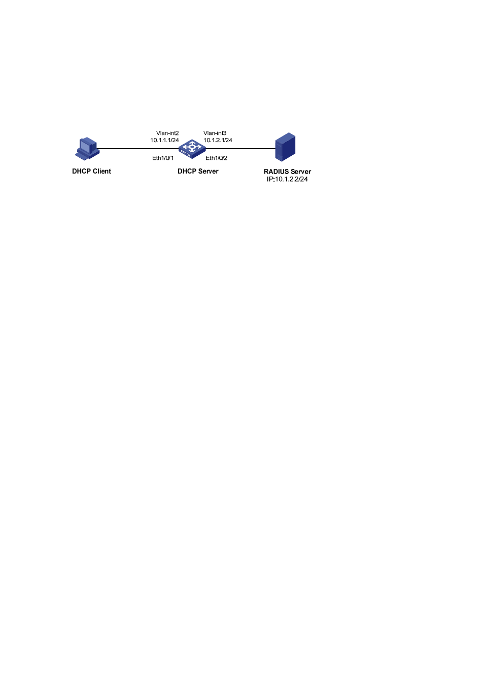
The IP address of VLAN-interface 1 is 10.1.1.1/24, and that of VLAN-interface 2 is 10.1.2.1/24.
z
The IP address of the RADIUS server is 10.1.2.2/24.
z
DHCP accounting is enabled on the DHCP server.
z
The IP addresses of the global DHCP address pool belongs to the network segment 10.1.1.0. The
DHCP server operates as a RADIUS client and adopts AAA for authentication.
Network diagram
Figure 2-4 Network diagram for DHCP accounting configuration
Configuration procedure
# Enter system view.
# Create VLAN 2.
[Sysname] vlan 2
[Sysname-vlan2] quit
# Create VLAN 3.
[Sysname] vlan 3
[Sysname-vlan3] quit
# Enter Ethernet 1/0/1 port view and add the port to VLAN 2.
[Sysname] interface ethernet 1/0/1
[Sysname-Ethernet1/0/1] port access vlan 2
[Sysname-Ethernet1/0/1] quit
# Enter Ethernet 1/0/2 port view and add the port to VLAN 3.
[Sysname] interface ethernet 1/0/2
[Sysname-Ethernet1/0/2] port access vlan 3
[Sysname-Ethernet1/0/2] quit
# Enter VLAN 2 interface view and assign the IP address 10.1.1.1/24 to the VLAN interface.
[Sysname] interface vlan-interface 2
[Sysname-Vlan-interface2] ip address 10.1.1.1 24
[Sysname-Vlan-interface2] quit
# Enter VLAN 3 interface view and assign the IP address 10.1.2.1/24 to the VLAN interface.
[Sysname] interface vlan-interface 3
[Sysname-Vlan-interface3] ip address 10.1.2.1 24
[Sysname-Vlan-interface3] quit
# Create a domain and a RADIUS scheme. Associate the domain with the RADIUS scheme.
[Sysname] radius scheme 123
[Sysname-radius-123] primary authentication 10.1.2.2
[Sysname-radius-123] primary accounting 10.1.2.2