Configuration procedure, Example for applying acls to hardware, Basic acl configuration example – H3C Technologies H3C S3100 Series Switches User Manual
Page 573: Network requirements, Network diagram
1-16
Configuration procedure
# Define ACL 2001.
[Sysname] acl number 2001
[Sysname-acl-basic-2001] rule 1 permit source 10.110.100.46 0
[Sysname-acl-basic-2001] quit
# Reference ACL 2001 to control users logging in to the Web server.
[Sysname] ip http acl 2001
Example for Applying ACLs to Hardware
Basic ACL Configuration Example
Network requirements
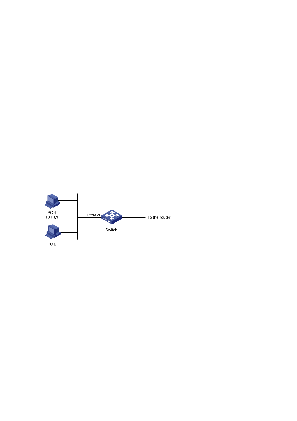
PC 1 and PC 2 connect to the switch through Ethernet 1/0/1. PC1’s IP address is 10.1.1.1. Apply an
ACL on Ethernet 1/0/1 to deny packets with the source IP address of 10.1.1.1 from 8:00 to 18:00
everyday.
Network diagram
Figure 1-3 Network diagram for basic ACL configuration
Configuration procedure
# Define a periodic time range that is active from 8:00 to 18:00 everyday.
[Sysname] time-range test 8:00 to 18:00 daily
# Define ACL 2000 to filter packets with the source IP address of 10.1.1.1.
[Sysname] acl number 2000
[Sysname-acl-basic-2000] rule 1 deny source 10.1.1.1 0 time-range test
[Sysname-acl-basic-2000] quit
# Apply ACL 2000 on Ethernet 1/0/1.
[Sysname] interface Ethernet1/0/1
[Sysname-Ethernet1/0/1] packet-filter inbound ip-group 2000