Configuration procedure, Network requirements, Network diagram – H3C Technologies H3C S3100 Series Switches User Manual
Page 494
1-10
z
Add a static ARP entry, with the IP address being 192.168.1.1, the MAC address being
000f-e201-0000, and the outbound port being Ethernet1/0/10 of VLAN 1.
Configuration procedure
[Sysname] undo arp check enable
[Sysname] arp timer aging 10
[Sysname] arp static 192.168.1.1 000f-e201-0000 1 Ethernet1/0/10
ARP Attack Detection and Packet Rate Limit Configuration Example
Network requirements
As shown in
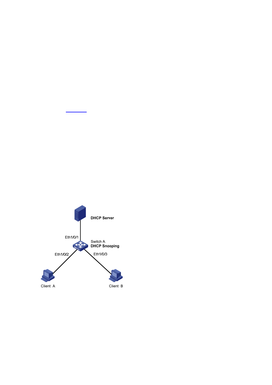
, Ethernet1/0/1 of Switch A (S3100-EI) connects to DHCP Server; Ethernet1/0/2
connects to Client A, Ethernet1/0/3 connects to Client B. Ethernet1/0/1, Ethernet1/0/2 and
Ethernet1/0/3 belong to VLAN 1.
z
Enable DHCP snooping on Switch A and specify Ethernet1/0/1 as the DHCP snooping trusted port.
z
Enable ARP attack detection in VLAN 1 to prevent ARP man-in-the-middle attacks, and specify
Ethernet1/0/1 as the ARP trusted port.
z
Enable the ARP packet rate limit function on Ethernet1/0/2 and Ethernet1/0/3 of Switch A, so as to
prevent Client A and Client B from attacking Switch A through ARP traffic.
z
Enable the port state auto recovery function on the ports of Switch A, and set the recovery interval
to 200 seconds.
Network diagram
Figure 1-4 ARP attack detection and packet rate limit configuration
Configuration procedure
# Enable DHCP snooping on Switch A.
[SwitchA] dhcp-snooping
# Specify Ethernet1/0/1 as the DHCP snooping trusted port and the ARP trusted port.
[SwitchA] interface Ethernet1/0/1
[SwitchA-Ethernet1/0/1] dhcp-snooping trust