Network requirements, Configuration procedures – H3C Technologies H3C S3100 Series Switches User Manual
Page 356
5-12
z
For details about the qos-profile, qos-profile port-based and undo qos-profile port-based
commands, refer to QoS-QoS Profile Operation.
z
A IPv6 multicast user control policy functions only if 802.1x is configured, that is, 802.1x must be
enabled on the port to which the QoS profile is applied. For details about 802.1x, refer to
802.1x-System Guard Operation.
z
An IPv6 multicast user control policy is functionally similar to an IPv6 multicast group filter. A
difference lies in that a control policy can control both multicast joining and leaving of users based
on authentication and authorization, while a multicast group filter is configured on a port to control
only multicast joining but not leaving of users without authentication or authorization.
IPv6 Multicast User Control Policy Configuration Example
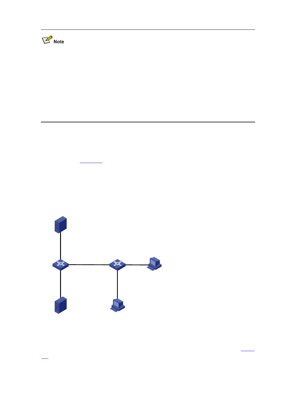
Network requirements
z
As shown in
, Switch A is a Layer-3 switch. It connects to IPv6 multicast Source 1
through VLAN-interface 101. It connects to the RADIUS server through VLAN-interface 102 and to
the Layer-2 switch, Switch B, through VLAN-interface 103.
z
Switch A runs MLDv1 and Switch B runs MLDv2 snooping. Hosts run 802.1x client.
z
An IPv6 multicast user control policy is configured on Switch B so that Host A can join or leave only
multicast group FF1E::101.
Figure 5-2 Network diagram for IPv6 multicast user control policy configuration
Switch B
Receiver
Host A
Host B
Eth1/0/2
Eth1/0/3
Eth1/0/1
Source 1
1::1/64
Eth1/0/1
Vlan-int101
1::2/24
Eth1/0/3
Vlan-int103
3001::1/64
Eth1/0/2
Vlan-int102
2::2/64
RADIUS server
2::1/64
Switch A
Configuration procedures
1) Configure IP addresses for interfaces
Enable IPv6 forwarding and configure an IP address and prefix length for each interface as per
. The configuration steps are omitted here.
2) Configure Switch A