Configuration example, Configuring ntp server/client mode, Network requirements – H3C Technologies H3C S3100 Series Switches User Manual
Page 705: Network diagram, Configuration procedure
1-15
Operation
Command
Description
Display the brief information about NTP servers
along the path from the local device to the
reference clock source
display ntp-service trace
Configuration Example
Configuring NTP Server/Client Mode
Network requirements
z
The local clock of Device A (a switch) is to be used as a master clock, with the stratum level of 2.
z
Device A is used as the NTP server of Device B (an S3100 Ethernet switch)
z
Configure Device B to work in the client mode, and then Device A will automatically work in the
server mode.
Network diagram
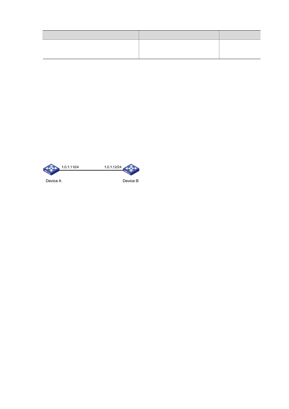
Figure 1-6 Network diagram for the NTP server/client mode configuration
Configuration procedure
Perform the following configurations on Device B.
# View the NTP status of Device B before synchronization.
Clock status: unsynchronized
Clock stratum: 16
Reference clock ID: none
Nominal frequency: 100.0000 Hz
Actual frequency: 100.0000 Hz
Clock precision: 2^18
Clock offset: 0.0000 ms
Root delay: 0.00 ms
Root dispersion: 0.00 ms
Peer dispersion: 0.00 ms
Reference time: 00:00:00.000 UTC Jan 1 1900 (00000000.00000000)
# Set Device A as the NTP server of Device B.
[DeviceB] ntp-service unicast-server 1.0.1.11
# (After the above configurations, Device B is synchronized to Device A.) View the NTP status of Device
B.
[DeviceB] display ntp-service status
Clock status: synchronized
Clock stratum: 3
Reference clock ID: 1.0.1.11
Nominal frequency: 100.0000 Hz