Bgp gr configuration, Network requirements, Configuration procedure – H3C Technologies H3C S7500E Series Switches User Manual
Page 274
6-71
Summary Count : 1
Destination: 1.1.1.0/24
Protocol: BGP Process ID: 0
Preference: 0 Cost: 100
NextHop: 2.0.1.1 Interface: Vlan-interface201
BkNextHop: 0.0.0.0 BkInterface:
RelyNextHop: 2.0.2.1 Neighbor : 2.0.1.1
Tunnel ID: 0x0 Label: NULL
State: Active Adv Age: 00h09m54s
Tag: 0
The above output shows that Switch C has one route to reach network 1.1.1.0/24, that is, Switch
C<—>Switch D<—>Switch A.
BGP GR Configuration
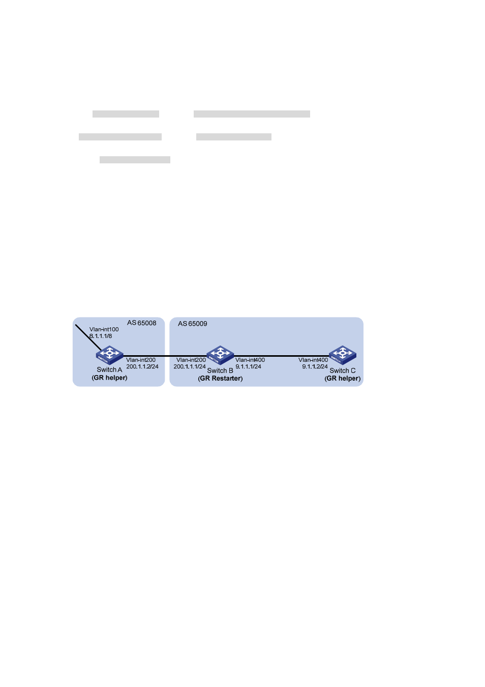
Network requirements
In the following figure are all BGP switches. Between Switch A and Switch B is an eBGP connection.
Switch B and Switch C are connected over an iBGP connection. Enable GR Capability for BGP so that
the communication between Switch A and Switch C is not affected when an active/standby main board
switchover occurs on Switch B.
Figure 6-28 Network diagram for BGP GR configuration
Configuration procedure
1) Configure Switch A
# Configure IP addresses for interfaces (omitted).
# Configure the eBGP connection.
[SwitchA] bgp 65008
[SwitchA-bgp] router-id 1.1.1.1
[SwitchA-bgp] peer 200.1.1.1 as-number 65009
# Inject network 8.0.0.0/8 to the BGP routing table.
[SwitchA-bgp] network 8.0.0.0
# Enable GR capability for BGP.
[SwitchA-bgp] graceful-restart
2) Configure Switch B
# Configure IP addresses for interfaces (omitted).
# Configure the eBGP connection.
[SwitchB] bgp 65009