Configuring bfd for bgp, Network requirements, Configuration procedure – H3C Technologies H3C S7500E Series Switches User Manual
Page 270
6-67
BGP Local router ID is 194.1.1.1
Status codes: * - valid, > - best, d - damped,
h - history, i - internal, s - suppressed, S - Stale
Origin : i - IGP, e - EGP, ? - incomplete
Network NextHop MED LocPrf PrefVal Path/Ogn
*>i 1.0.0.0 193.1.1.1 0 200 0 100i
* i 192.1.1.1 0 100 0 100i
You can find route 1.0.0.0/8 from Switch D to Switch C is the optimal.
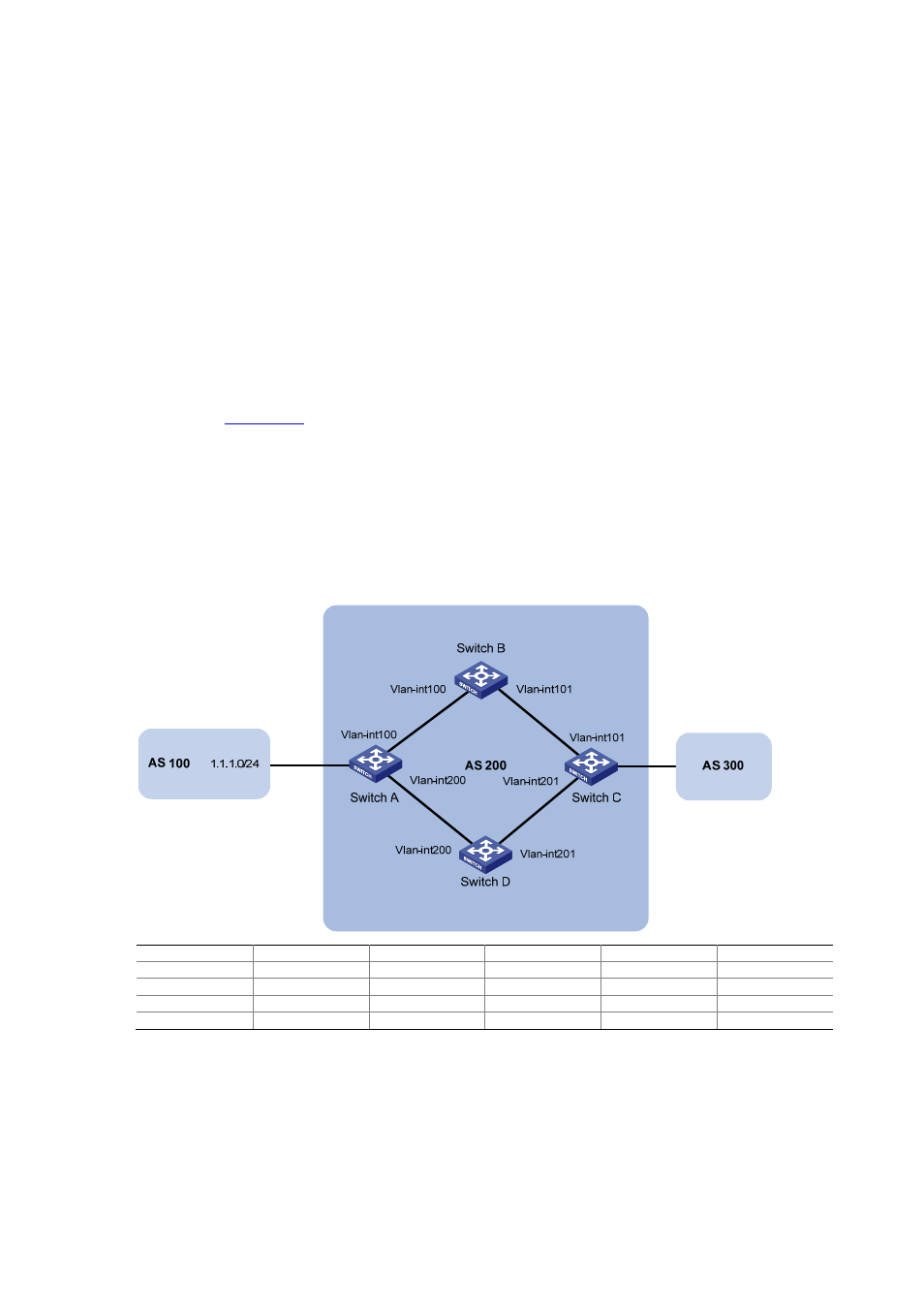
Configuring BFD for BGP
Network requirements
As shown in
z
Configure OSPF as the IGP in AS 200.
z
Establish two iBGP connections between Switch A and Switch C. When both links are working,
Switch C adopts the link Switch A<—>Switch B<—>Switch C to exchange packets with network
1.1.1.0/24. Configure BFD over the link. Then if the link fails, BFD can quickly detect the failure
and notify it to BGP. Then the link Switch A<—>Switch D<—>Switch C takes effect immediately.
Figure 6-27 Network diagram for BFD for BGP configuration
Device Interface
IP
address
Device Interface
IP
address
Switch A
Vlan-int100
3.0.1.1/24
Switch C
Vlan-int101
3.0.2.2/24
Vlan-int200
2.0.1.1/24
Vlan-int201
2.0.2.2/24
Switch B
Vlan-int100
3.0.1.2/24
Switch D
Vlan-int200
2.0.1.2/24
Vlan-int101
3.0.2.1/24
Vlan-int201
2.0.2.1/24
Configuration procedure
Configure IP addresses for interfaces (omitted).
Configure OSPF (omitted) to ensure that Switch A and Switch C are reachable to each other.
Configure BGP on Switch A.
# Establish two iBGP connections between Switch A and Switch C.