Configuration procedure – H3C Technologies H3C S7500E Series Switches User Manual
Page 252
6-49
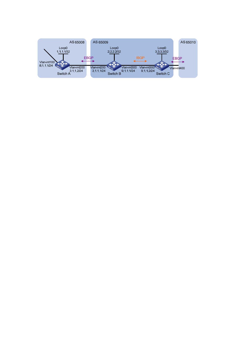
Figure 6-20 Network diagram for BGP basic configuration (on switches)
Configuration procedure
1) Configure IP addresses for interfaces (omitted)
2) Configure
iBGP
z
To prevent route flapping caused by port state changes, this example uses loopback interfaces to
establish iBGP connections.
z
Because loopback interfaces are virtual interfaces, you need to use the peer connect-interface
command to specify the loopback interface as the source interface for establishing BGP
connections.
z
Enable OSPF in AS 65009 to ensure that Switch B can communicate with Switch C through
loopback interfaces.
# Configure Switch B.
[SwitchB] bgp 65009
[SwitchB-bgp] router-id 2.2.2.2
[SwitchB-bgp] peer 3.3.3.3 as-number 65009
[SwitchB-bgp] peer 3.3.3.3 connect-interface loopback 0
[SwitchB-bgp] quit
[SwitchB] ospf 1
[SwitchB-ospf-1] area 0
[SwitchB-ospf-1-area-0.0.0.0] network 2.2.2.2 0.0.0.0
[SwitchB-ospf-1-area-0.0.0.0] network 9.1.1.1 0.0.0.255
[SwitchB-ospf-1-area-0.0.0.0] quit
[SwitchB-ospf-1] quit
# Configure Switch C.
[SwitchC] bgp 65009
[SwitchC-bgp] router-id 3.3.3.3
[SwitchC-bgp] peer 2.2.2.2 as-number 65009
[SwitchC-bgp] peer 2.2.2.2 connect-interface loopback 0
[SwitchC-bgp] quit
[SwitchC] ospf 1
[SwitchC-ospf-1] area 0
[SwitchC-ospf-1-area-0.0.0.0] network 3.3.3.3 0.0.0.0
[SwitchC-ospf-1-area-0.0.0.0] network 9.1.1.0 0.0.0.255
[SwitchC-ospf-1-area-0.0.0.0] quit
[SwitchC-ospf-1] quit
[SwitchC] display bgp peer
BGP local router ID : 3.3.3.3
Local AS number : 65009