Bgp and igp synchronization configuration, Network requirements, Configuration procedure – H3C Technologies H3C S7500E Series Switches User Manual
Page 255
6-52
5) Verification
# Ping 8.1.1.1 on Switch C.
[SwitchC] ping 8.1.1.1
PING 8.1.1.1: 56 data bytes, press CTRL_C to break
Reply from 8.1.1.1: bytes=56 Sequence=1 ttl=254 time=2 ms
Reply from 8.1.1.1: bytes=56 Sequence=2 ttl=254 time=2 ms
Reply from 8.1.1.1: bytes=56 Sequence=3 ttl=254 time=2 ms
Reply from 8.1.1.1: bytes=56 Sequence=4 ttl=254 time=2 ms
Reply from 8.1.1.1: bytes=56 Sequence=5 ttl=254 time=2 ms
--- 8.1.1.1 ping statistics ---
5 packet(s) transmitted
5 packet(s) received
0.00% packet loss
round-trip min/avg/max = 2/2/2 ms
BGP and IGP Synchronization Configuration
Network requirements
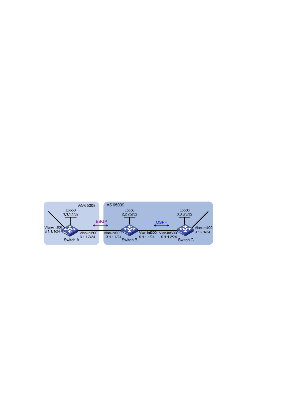
As shown below, all devices of company A belong to AS 65008 while all devices of company B belong
to AS 65009. AS 65008 and AS 65009 are connected through Switch A and Switch B. It isi required
that Switch A can access network 9.1.2.0/24 in AS 65009, and Switch C can access network 8.1.1.0/24
in AS 65008.
Figure 6-21 Network diagram for BGP and IGP synchronization
Configuration procedure
1) Configure IP addresses for interfaces (omitted)
2) Configure
OSPF
Enable OSPF in AS 65009, so that Switch B can obtain the route to 9.1.2.0/24.
# Configure Switch B.
[SwitchB] ospf 1
[SwitchB-ospf-1] area 0
[SwitchB-ospf-1-area-0.0.0.0] network 2.2.2.2 0.0.0.0
[SwitchB-ospf-1-area-0.0.0.0] network 9.1.1.0 0.0.0.255
[SwitchB-ospf-1-area-0.0.0.0] quit
[SwitchB-ospf-1] quit
# Configure Switch C.
[SwitchC] ospf 1
[SwitchC-ospf-1] import-route direct
[SwitchC-ospf-1] area 0
[SwitchC-ospf-1-area-0.0.0.0] network 9.1.1.0 0.0.0.255