Configuring bfd for ospf, Network requirements, Configuration procedure – H3C Technologies H3C S7500E Series Switches User Manual
Page 142
4-73
3.1.1.0/24 O_ASE 150 1 10.2.1.2 Vlan200
3.1.2.0/24 O_ASE 150 1 10.2.1.2 Vlan200
10.1.1.0/24 Direct 0 0 10.1.1.1 Vlan100
10.1.1.1/32 Direct 0 0 127.0.0.1 InLoop0
10.2.1.0/24 Direct 0 0 10.2.1.1 Vlan200
10.2.1.1/32 Direct 0 0 127.0.0.1 InLoop0
10.3.1.0/24 OSPF 10 4 10.1.1.2 Vlan100
10.4.1.0/24 OSPF 10 13 10.2.1.2 Vlan200
127.0.0.0/8 Direct 0 0 127.0.0.1 InLoop0
127.0.0.1/32 Direct 0 0 127.0.0.1 InLoop0
The route destined for 10.5.1.1/24 is filtered out.
Configuring BFD for OSPF
Network requirements
z
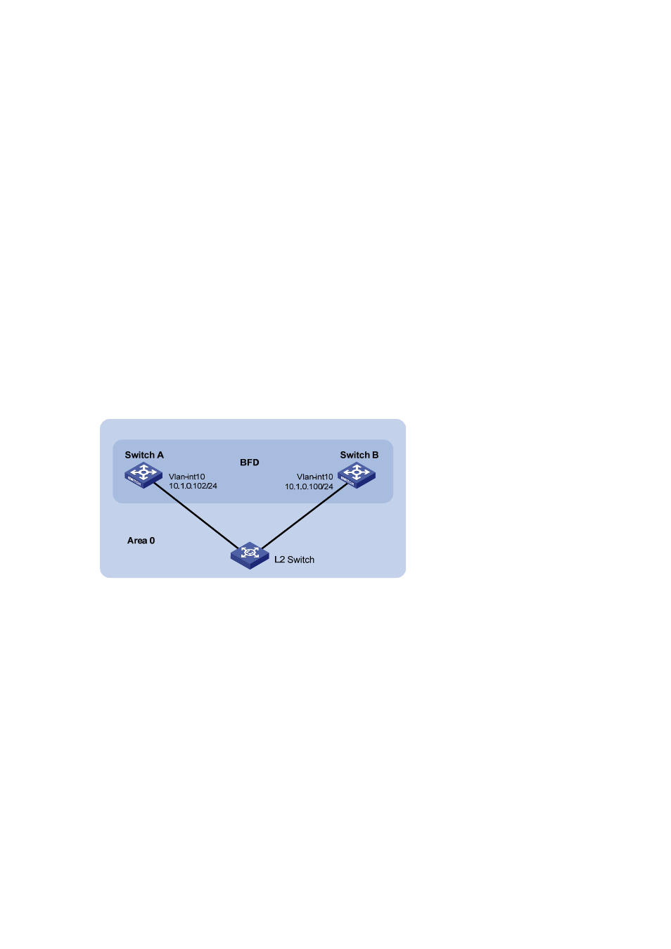
Switch A and Switch B are interconnected through a Layer 2 switch. BFD is enabled on the switch
interfaces. OSPF is enabled on the switches that are reachable to each other at the network layer.
z
When the link between Switch B and the Layer 2 switch fails, BFD can quickly detect the failure
and notify OSPF of the failure.
Figure 4-30 Network diagram for BFD configuration on an OSPF link
Configuration procedure
6) Configure IP addresses for interfaces (omitted)
Configure OSPF basic functions.
# Configure Switch A.
[SwitchA] ospf
[SwitchA-ospf-1] area 0
[SwitchA-ospf-1-area-0.0.0.0] network 10.1.0.0 0.0.0.255
[SwitchA-ospf-1-area-0.0.0.0] quit
[SwitchA-ospf-1] quit
[SwitchA] interface vlan 10
[SwitchA-Vlan-interface10] ospf bfd enable
[SwitchA-Vlan-interface10] quit
# Configure Switch B.
[SwitchB] ospf
[SwitchB-ospf-1] area 0