Verilink Access Manager 2000 (896-502037-001) Product Manual User Manual
Page 295
Displaying circuit status
Access Manager 2000 User Manual
8-25
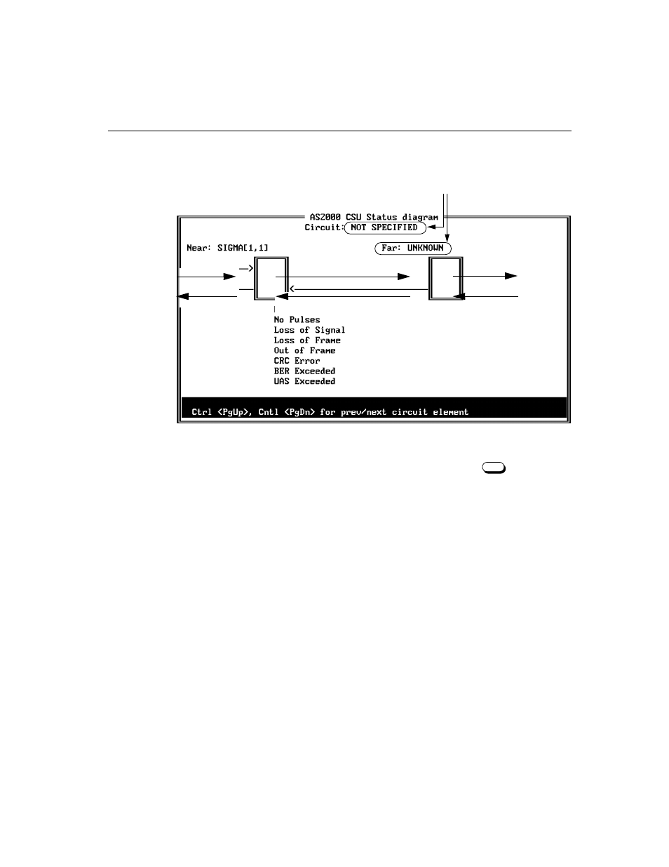
A status diagram like the one below will appear.
All possible error indications are shown in the screen above.
2. After viewing the current status diagram, press
to return to
the On-line Access Menu.
Alarms are shown at the location at which they occur. If alarms are
present, the DS1 line section in alarm appears in flashing red. If no
alarms are present, the line section is green (or blank if you are
using a monochrome display). Alarm designations are shown
flashing adjacent to the circuit section in which they occur.
Any change in status reported by the near-end CSU causes the
screen to be updated.
These display information when a circuit
and far-end circuit elements are defined.
F2
- 1061 T1 Multicast (34-00268) Product Manual (18 pages)
- 2010 (34-00204) Product Manual (15 pages)
- 1558A (34-00228) Product Manual (39 pages)
- 1558D (34-00255) Product Manual (42 pages)
- 210 (34-00196) Product Manual (9 pages)
- 2000 (34-00182) Product Manual (58 pages)
- 300 (34-00199) Product Manual (9 pages)
- 2048 (34-00179) Product Manual (33 pages)
- 400 (34-00222) Product Manual (9 pages)
- 2100 (34-00187) Product Manual (19 pages)
- 7200p Series IAD (34-00334.B) Product Manual (311 pages)
- APS 2000 T1 Line Protection (880-502411-001) Product Manual (87 pages)
- AS200 (896-502379-001) Product Manual (112 pages)
- AS420 (34-00294) Product Manual (28 pages)
- AS56/56Plus (896-502588-001) Product Manual (130 pages)
- 9000 Series (34-00271) Product Manual (440 pages)
- AS2000: The Basics (880-502981-001) Product Manual (179 pages)
- ConnecT 56K DSU (896-502110-001) Product Manual (88 pages)
- AS4000 (34-00244) Product Manual (210 pages)
- C150 (880-502893-001) Product Manual (135 pages)
- Craft Interface (No Part Number) Product Manual (8 pages)
- DDS Lite (34-00295.C) Product Manual (19 pages)
- DCSU 2911 (880-502647-001) Product Manual (79 pages)
- DIDCSU 2912 (880-502646-001) Product Manual (107 pages)
- DIU 2130 (880-503297-001) Product Manual (101 pages)
- DIU 2131 (880-502765-001) Product Manual (31 pages)
- FrameStart FSE (34-00291.F) Product Manual (49 pages)
- DPRI 2922 (880-503142-001) Product Manual (91 pages)
- HDM 2180 (880-503048-001) Product Manual (79 pages)
- HDM 2182 (880-502925-001) Product Manual (81 pages)
- IMUX (880-503137-001) Product Manual (48 pages)
- FrameStart FSM (34-00299.E) Product Manual (153 pages)
- TAC 2010 (880-503298-001) Product Manual (65 pages)
- M1-3 (880-503136-001) Product Manual (75 pages)
- NCC 2130 (880-503285-001) Product Manual (61 pages)
- NCM 2000 (880-502623-001) Product Manual (91 pages)
- NetPath 2000 Product Manual (30 pages)
- PRISM 3000 (34-00184) Product Manual (45 pages)
- PRISM 3001 (34-00186) Product Manual (58 pages)
- PRISM 3002 (34-00277) Product Manual (52 pages)
- Net Engine (3150-30626-001) Product Manual (323 pages)
- PRISM 3021 (34-00262) Product Manual (47 pages)
- PRISM 3010 Dual DSX-1 (34-00250.2) Product Manual (22 pages)
- PRISM 3060-10 (34-00252.4) Product Manual (76 pages)